Kirchhoff's Voltage And Current Laws
Kirchhoff's voltage and current laws, commonly referred to as Kirchhoff's laws or KVL (Kirchhoff's Voltage Law) and KCL (Kirchhoff's Current Law), are fundamental principles in the analysis of electrical circuits. They are named after the German physicist Gustav Kirchhoff, who introduced them in the mid-19th century. These laws are crucial for understanding and analyzing complex electrical networks.
Kirchhoff's Voltage Law (KVL)

KVL states that the algebraic sum of the voltages around any closed loop in a circuit is zero. In other words, the sum of the voltage rises must equal the sum of the voltage drops in a closed loop. Mathematically, it can be expressed as:-
Where represents the sum of all voltage rises and drops around a closed loop.
In the above figure, the sum of all the voltage drops around the loop is equal to zero:-
When you begin at any point of the loop and continue in the same direction, note the voltage drops in all the negative or positive directions and returns to the same point. It is essential to maintain the direction either counterclockwise or clockwise; otherwise, the final voltage value will not be zero.
KVL is based on the principle of conservation of energy, stating that the total energy delivered to a circuit loop must equal the total energy dissipated within that loop.
Click here to open youtube playlist containing numericals on KVL.
Kirchhoff's Current Law (KCL)

KCL states that the algebraic sum of currents entering a node (or a junction) in a circuit is zero. In other words, the sum of currents entering a node equals the sum of currents leaving the node. Mathematically, it can be expressed as:-
Where represents the sum of all currents entering and leaving a node.
In the fig 1, the currents , entering the node is considered positive, likewise, the current exiting the node is considered negative in values. This can be expressed in the form of an equation:
Similarly, In the fig 2, the currents , and entering the node are considered positive, This can be expressed in the form of an equation:
KCL is based on the principle of conservation of charge, stating that the total charge entering a node must equal the total charge leaving the node.
Click here to open youtube playlist containing numericals on KCL.
Numericals
Ques 1 - Find the value of the current passing through the resistance = 10 Ω in the circuit below using Kirchhoff's principles, when and both are equal and their value is 5 Ω.

Sol - Applying Kirchhoff's Law in the above circuit, Let's take the current 'i' passing through the loop in the clockwise direction:-
-10 + 5(i) + 5(i) + 10(i) + 5 = 0
20i - 5 = 0
20i = 5
i = 5 / 20 =1/4
The current passing through is 1/4 Ampere.
Ques 2 - If = 2Ω, = 4Ω, = 6Ω, determine the electric current that flows in the circuit below.
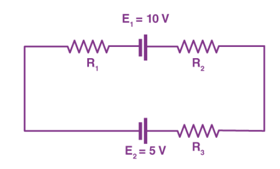
Sol - When the current flows across the resistor, there is a potential decrease. Hence, is signed negative. If the current moves from low to high, then the emf source is signed positive because of the energy charging at the emf source. Likewise, if the current moves from high to low voltage to , then the source of emf is signed negative because of the emptying of energy at the emf source. In this solution, the direction of the current is the same as the direction of clockwise rotation.
+ - - - = 0
Substituting the values in the equation, we get
-2I + 10 - 4I - 6I - 5 = 0
-12I + 5 = 0
I = -5/-12
I = 0.416 A The electric current that flows in the circuit is 0.416 A.
The electric current is signed positive which means that the direction of the electric current is the same as the direction of clockwise rotation. If the electric current is negative then the direction of the current would be in anti-clockwise direction.
Power Dissipation
Power dissipation in a circuit refers to the process by which electrical energy is converted into other forms of energy, typically heat, within the components of the circuit. The power dissipated in a component can be calculated using Ohm's Law and the Joule's Law. Here's how it works:
The power dissipated in a component can be calculated using Ohm's Law and the Joule's Law. Here's how it works:-
- Ohm's Law: Ohm's Law states that the voltage across a resistor is directly proportional to the current flowing through it, given by the equation .
- Joule's Law: Joule's Law states that the power dissipated by a resistor is equal to the product of the current flowing through it and the voltage across it, given by the equation
Combining Ohm's Law and Joule's Law, we can express power dissipation in terms of resistance and current as:-
Or, since = , we can also express it as:
These formulas are valid for resistive components like resistors. For other types of components like capacitors or inductors, power dissipation may be calculated differently or may not apply at all, as they store and release energy rather than dissipating it as heat.
Checkout one numerical on power dissipation.
Voltage Source And Current Source
Voltage sources and current sources are fundamental components used to supply power to electrical circuits. Both ideal and practical versions of these sources exist, each with its characteristics and implications.
Ideal Voltage Source
An ideal voltage source maintains a constant voltage across its terminals, regardless of the current flowing through it or the load connected to it. In other words, it provides a fixed voltage output regardless of the current drawn from it. The ideal voltage source has zero internal resistance.
-
Symbol: The symbol for an ideal voltage source is a circle with a plus sign (+) and a minus sign (-) representing the positive and negative terminals, respectively, with an arrow indicating the direction of the voltage.
-
Mathematical Representation: An ideal voltage source is represented by the equation:
where is the fixed voltage output.
Practical Voltage Source
In reality, voltage sources have limitations due to factors like internal resistance, which can cause the voltage to drop under load conditions. A practical voltage source is represented as an ideal voltage source in series with an internal resistance .
-
Mathematical Representation: A practical voltage source can be represented by the equation:
where is the current flowing through the source.
Ideal Current Source
An ideal current source provides a constant current regardless of the voltage across it or the load connected to it. It maintains a fixed current output irrespective of the voltage drop across the load. The ideal current source has infinite internal resistance.
-
Symbol: The symbol for an ideal current source is an arrow indicating the direction of current flow.
-
Mathematical Representation: An ideal current source is represented by the equation:
where is the fixed current output.
Practical Current Source
Practical current sources have limitations due to factors like internal resistance, which can cause the current to vary under load conditions. A practical current source is represented as an ideal current source in parallel with an internal resistance .
-
Mathematical Representation: A practical voltage source can be represented by the equation:
where is the voltage across the source.
Voltage and Current Division Rule
Current Division Rule
The current division rule is used to determine how the total current entering a parallel network is distributed among the individual parallel branches.
In a parallel circuit, where multiple resistors are connected across the same voltage source, the current division rule states that the current through each resistor is inversely proportional to its resistance. Mathematically, it can be expressed as follows:
Where:
- is the current through the resistor,
- is the total voltage across the parallel circuit (applied voltage),
- is the resistance of the resistor.
Consider a parallel circuit with two resistors and connected in parallel, each containing current and respectively

-
Total Conductance: Conductance G is the reciprocal of resistance R. The total conductance of the parallel combination is the sum of the individual conductances:
=
=
= + = +
-
Equivalent Resistance:
The equivalent resistance of the parallel combination is the reciprocal of the total conductance:
= =
-
Total Current:
The total current I entering the parallel network splits into currents and through and respectively.
-
Voltage Across Parallel Combination:
The voltage V across the parallel combination is the same for both resistors. Using Ohm's law:
= =
-
Currents in Each Resistor:
Using Ohm's law for each resistor and the fact that the total current is the sum of the individual currents:
=
=
= +
-
Current Division Formula:
Solving for and :
=
=
Numerical
Ques: Consider a parallel circuit with two resistors, = and = , and a total current I=9A entering the parallel network.
Sol:
-
Find current through
= = = 6A
-
Find current through
= = = 3A
Voltage Division Rule
The voltage division rule is used to determine the voltage drop across each resistor in a series circuit. This rule states that the voltage drop across each resistor is directly proportional to its resistance and inversely proportional to the sum of the resistances in the series.
In a series circuit, where multiple resistors are connected in a chain with the same current flowing through each resistor, the voltage division rule states that the voltage across each resistor is proportional to its resistance. Mathematically, it can be expressed as follows:
Where:
- is the voltage across the resistor,
- is the total voltage across the series circuit,
- is the resistance of the resistor.
- is the total resistance of the series circuit, which is the sum of all individual resistances.

-
Total Resistance:
= +
-
Voltage across :
=
-
Voltage across :
=
Numerical
Ques: Consider a series circuit with a voltage source , and two resistors and
Sol:
-
Voltage across :
= = = 8V
-
Voltage across :
= = = 12V
