RC Phase Shift Oscillator

Analysis of RC Circuit

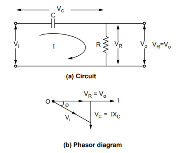
The basic RC network is shown in Fig. (a), with the output taken across the resistor RR.

rc_circuit
  • The capacitive reactance XCX_C is given by: XC=12πfC ΩX_C = \frac{1}{2\pi f C} \text{ Ω} where ff is the frequency of the input.

  • The total impedance of the circuit is: Z=RjXC=Rj(12πfC) ΩZ = R - jX_C = R - j\left(\frac{1}{2\pi f C}\right) \text{ Ω}

    =Zϕ Ω(i)= |Z|\angle -\phi^\circ \text{ Ω} \quad \text{(i)}

  • The current II flowing in the circuit is: I=Vi0Z=Vi0ZϕI = \frac{V_i \angle 0^\circ}{Z} = \frac{V_i \angle 0^\circ}{|Z|\angle -\phi^\circ}

    =ViZ+ϕ A(ii)= \frac{V_i}{|Z|}\angle +\phi^\circ \text{ A} \quad \text{(ii)}

    Therefore: Z=R2+XC2andϕ=tan1(XCR)|Z| = \sqrt{R^2 + X_C^2} \quad \text{and} \quad \phi = \tan^{-1}\left(\frac{X_C}{R}\right)

    Z=R2+XC2andϕ=tan1(XCR)|Z| = \sqrt{R^2 + X_C^2} \quad \text{and} \quad \phi = \tan^{-1}\left(\frac{X_C}{R}\right)

The equation (ii) shows that the current II leads the input voltage by angle ϕ\phi.

  • The output voltage VoV_o is the drop across RR: Vo=VR=I×R(iii)V_o = V_R = I \times R \quad \text{(iii)}

  • The output voltage is in phase with the current, hence it leads the input voltage by angle ϕ\phi.

  • Thus, the RC circuit introduces a phase shift ϕ\phi between the input and output, which depends on RR, CC, and frequency ff.

RC Feedback Network for Phase Shift

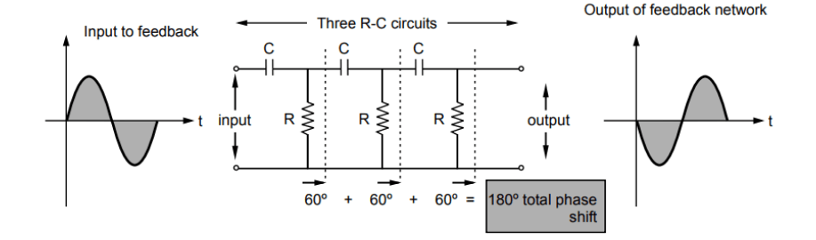
  • In an RC phase shift oscillator, the amplifier introduces a phase shift of 180180^\circ.

  • Thus, the feedback network must introduce a phase shift of 180180^\circ to satisfy the Barkhausen criterion.

  • The RC feedback network consists of three RC sections, each contributing 6060^\circ phase shift.

  • Hence, the feedback network consists of three RC sections, as shown in the figure.

    feedback_network
  • In all three sections, resistance and capacitance values are the same, ensuring each section produces precisely 6060^\circ phase shift at a particular frequency. This frequency is the operating frequency of the oscillator.

Transistorized RC Phase Shift Oscillator

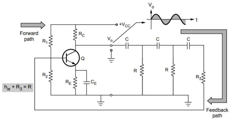
The figure shows an RC phase shift oscillator using a BJT amplifier stage in a common emitter configuration.

transistorised
  • The output of the common emitter amplifier is connected as input to the RC phase-shifting network.

  • The output of the RC phase-shifting network is connected as input to the amplifier.

  • The common emitter amplifier introduces a phase shift of 180180^\circ between its input and output.

  • The RC phase-shifting network contributes another 180180^\circ phase shift, making the total phase shift around the loop 360360^\circ.

Neglecting R1R_1 and R2R_2, the input impedance of the amplifier stage is hieh_{ie}:

  • To have all three resistance values in the RC sections equal, the resistance in the last section is selected as R3R_3 such that: R3+hie=RR_3 + h_{ie} = R

    R3=Rhie(iv)R_3 = R - h_{ie} \quad \text{(iv)}

  • If R1R_1 and R2R_2 are not neglected: R3=R[R1R2hie](v)R_3 = R - [R_1 \parallel R_2 \parallel h_{ie}] \quad \text{(v)}

  • When the gain AA of the amplifier stage and feedback factor β\beta are adjusted to give Aβ=1|A \beta | = 1, the circuit will work as an oscillator, satisfying both the Barkhausen conditions.

Sure, let's go through the derivation of the frequency of oscillations for the RC phase shift oscillator in detail:

Derivation of Frequency of Oscillations
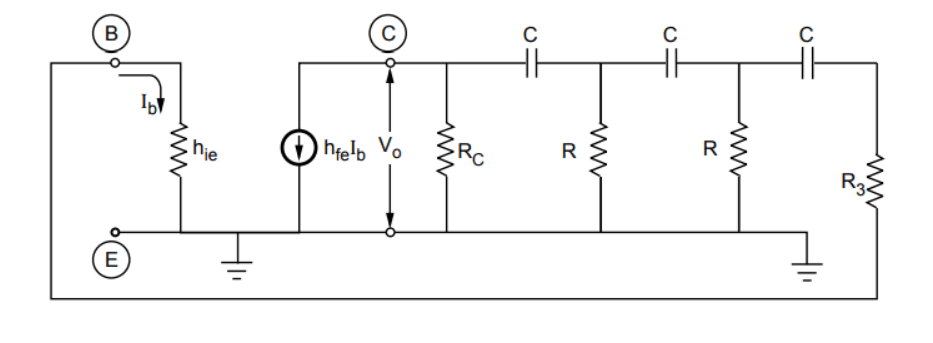
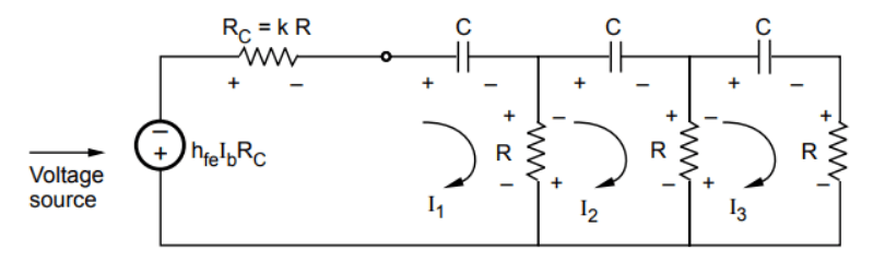
  1. Equivalent Circuit:

    Replace the transistor with its approximate hh-parameter model as shown in the figure.

    Equivalent h-parameter model
    • The total resistance RR in the circuit is given by: R=hie+R3R = h_{ie} + R_3 where hieh_{ie} is the input resistance of the transistor, and R3R_3 is the resistance in the RC network.

    • The resistance RCR_C in the RC network is related to RR by a factor kk: RCR=k\frac{R_C}{R} = k Thus: RC=kRR_C = kR

    • The modified equivalent circuit is shown below.

      Modified Equivalent Circuit
  2. Applying KVL:

    Apply Kirchhoff's Voltage Law (KVL) to the three loops in the circuit:

    • Loop 1 (across RCR_C, 1jωC\frac{1}{j\omega C}, and RR): I1RC1jωCI1R(I1I2)hfeIbRC=0-I_1 R_C - \frac{1}{j\omega C} I_1 - R(I_1 - I_2) - h_{fe} I_b R_C = 0

      Substituting RC=kRR_C = kR: I1[kR+R+1jωC]+I2R=hfeIbkR-I_1 \left[kR + R + \frac{1}{j\omega C}\right] + I_2 R = h_{fe} I_b kR

      I1[kR+R+1jωC]+I2R=hfeIbkR(vi)-I_1 \left[kR + R + \frac{1}{j\omega C}\right] + I_2 R = h_{fe} I_b kR \quad \text{(vi)}

    • Loop 2 (across 1jωC\frac{1}{j\omega C}, RR, and RR): 1jωCI2R(I2I1)R(I2I3)=0-\frac{1}{j\omega C} I_2 - R(I_2 - I_1) - R(I_2 - I_3) = 0

      I1RI2(2R+1jωC)+I3R=0I_1 R - I_2 \left(2R + \frac{1}{j\omega C}\right) + I_3 R = 0

      I1RI2(2R+1jωC)+I3R=0(vii)I_1 R - I_2 \left(2R + \frac{1}{j\omega C}\right) + I_3 R = 0 \quad \text{(vii)}

    • Loop 3 (across 1jωC\frac{1}{j\omega C}, RR, and RR): 1jωCI3I3RR(I3I2)=0-\frac{1}{j\omega C} I_3 - I_3 R - R(I_3 - I_2) = 0

      I2RI3(2R+1jωC)=0I_2 R - I_3 \left(2R + \frac{1}{j\omega C}\right) = 0

      I2RI3(2R+1jωC)=0(viii)I_2 R - I_3 \left(2R + \frac{1}{j\omega C}\right) = 0 \quad \text{(viii)}

  3. Solving Using Cramer's Rule:

    Construct the determinant DD from the above equations:

    D=(k+1)R1sC+R0R2R1sCR0R2R1sCD = \begin{vmatrix} -(k+1)R - \frac{1}{sC} & +R & 0 \\ R & -2R - \frac{1}{sC} & R \\ 0 & R & -2R - \frac{1}{sC} \end{vmatrix}

    Solving this determinant:

    D=s3C3R3(3k+1)+s2C2R2(4k+6)+sRC(5+k)+1s3C3D = -\frac{s^3 C^3 R^3 (3k+1) + s^2 C^2 R^2 (4k+6) + sRC(5+k) + 1}{s^3 C^3} (ix)\quad \text{(ix)}

    Find D3D_3 to solve for I3I_3:

    D3=(k+1)R1sCRhfeIbkRR2R1sC00R0=D_3 = \begin{vmatrix} -(k+1)R - \frac{1}{sC} & R & h_{fe} I_b kR \\ R & -2R - \frac{1}{sC} & 0 \\ 0 & R & 0 \end{vmatrix} =

    kR3hfeIbkR^3 h_{fe} I_b

    D3=kR3hfeIb(x)D_3 = kR^3 h_{fe} I_b \quad \text{(x)}

    Therefore:

    I3=D3D=kR3hfeIbs3C3s3C3R3(3k+1)+s2C2R2(4k+6)+sRC(5+k)+1I_3 = \frac{D_3}{D} = \frac{-kR^3 h_{fe} I_b s^3 C^3}{s^3 C^3 R^3 (3k+1) + s^2 C^2 R^2 (4k+6) + sRC(5+k) + 1}

    (xi)\quad \text{(xi)}

    The transistor current gain hfeh_{fe} and β\beta are related by:

    β=I3hfeIb\beta = \frac{I_3}{h_{fe} I_b}

    A=I3Ib=hfeA = \frac{I_3}{I_b} = h_{fe}

    Therefore:

    Aβ=hfe×I3hfeIb=I3IbA \beta = h_{fe} \times \frac{I_3}{h_{fe} I_b} = \frac{I_3}{I_b}

    Aβ=I3Ib (xii)A \beta = \frac{I_3}{I_b} \text{ (xii)}

  4. Frequency Calculation:

    From equations (xii) and (xi),

    Aβ=k R3 hfe s3C3s3C3R3(3k+1)+s2C2R2(4k+6)+sRC(5+k)+1A \beta \quad = \quad \frac{-k \ R^3 \ h_{fe} \ s^3 C^3}{s^3 C^3 R^3 (3k+1) + s^2 C^2 R^2 (4k+6) + sRC(5+k) + 1}

    (xiii)\quad \text{(xiii)}

    Using s=jω,            s2=+j2ω2=ω2,            s3=j3ω3=jω3s = j\omega, \; \; \; \; \; \; s^2 = +j^2 \omega^2 = -\omega^2, \; \; \; \; \; \; s^3 = j^3 \omega^3 = -j\omega^3 and

    Separating the real and imaginary parts we get,

    Aβ=+jω3 k R3 C3 hfe[14 k ω2C2R26 ω2C2R2]j ω[3 kω2R3C3+ω2R3C35RCkRC]A \beta = \frac{+ j\omega^3 \ k \ R^3 \ C^3 \ h_{fe}}{[1 - 4 \ k \ \omega^2 C^2 R^2 - 6 \ \omega^2 C^2 R^2] - j \ \omega [3 \ k \omega^2 R^3 C^3 + \omega^2 R^3 C^3 - 5 RC - kRC]}

    Dividing numerator and denominator by  jω3R3C3\ j\omega^3 R^3 C^3 and replacing  1j=+j\ -\frac{1}{j}= +j

    Aβ=khfej{1ω3R3C34kωRC6ωRC}{3k+15ω2R2C2kω2R2C2}A\beta = \frac{k h_{fe}}{-j \left\{ \frac{1}{\omega^3 R^3 C^3} - \frac{4k}{\omega RC} - \frac{6}{\omega RC} \right\} - \left\{ 3k + 1 - \frac{5}{\omega^2 R^2 C^2} - \frac{k}{\omega^2 R^2 C^2} \right\}}

        Aβ=khfe[33k1+5α2+kα2]j[α34kα6α](xiv)\therefore \; \; A \beta = \frac{k h_{fe}}{-\left[3 - 3k - 1 + 5 \alpha^2 + k \alpha^2\right] - j \left[\alpha^3 - 4k \alpha - 6 \alpha\right]} \quad \text{(xiv)}

    where α=1ωRC\alpha = \frac{1}{\omega RC}.

    To satisfy the Barkhausen criterion (Aβ=0\angle A\beta = 0^\circ), the imaginary part must be zero:

    α34kα6α=0\alpha^3 - 4k \alpha - 6 \alpha = 0

    α(α24k6)=0\alpha(\alpha^2 - 4k - 6) = 0

    α2=4k+6\alpha^2 = 4k + 6

    1ωRC=4k+6\frac{1}{\omega RC} = \sqrt{4k + 6}

    ω=1RC4k+6\omega = \frac{1}{RC \sqrt{4k + 6}}

    f=12πRC4k+6f = \frac{1}{2 \pi RC \sqrt{4k + 6}}

    Thus, the frequency of oscillations is:

    f=12πRC4k+6(xv) f = \frac{1}{2 \pi RC \sqrt{4k + 6}} \quad \text{(xv)}

    Minimum Value of hfeh_{fe}:

    Substituting α=4k+6\alpha = \sqrt{4k + 6} in equation (xiv),

    Aβ=khfe3k1+(4k+6)(5+k)=khfe4k2+23k+29A\beta = \frac{k h_{fe}}{-3k - 1 + (4k + 6)(5 + k)} = \frac{k h_{fe}}{4k^2 + 23k + 29}

    For Aβ=1|A \beta| = 1:

    khfe4k2+23k+29=1\frac{k h_{fe}}{4k^2 + 23k + 29} = 1

    hfe=4k+23+29kh_{fe} = 4k + 23 + \frac{29}{k}

    To find the minimum value of hfeh_{fe}, differentiate with respect to kk:

    ddk[4k+23+29k]=0\frac{d}{dk} \left[ 4k + 23 + \frac{29}{k} \right] = 0

    429k2=04 - \frac{29}{k^2} = 0

    k2=294k^2 = \frac{29}{4}

    k=2.6925 for minimum hfek = 2.6925 \text{ for minimum } h_{fe}

    Substituting k=2.6925k = 2.6925:

    hfe(min)=4×2.6925+23+292.6925=44.54h_{fe(min)} = 4 \times 2.6925 + 23 + \frac{29}{2.6925} = 44.54

    Thus, the transistor must have hfe44.54h_{fe} \geq 44.54 for the circuit to oscillate.

Advantages of RC Phase Shift Oscillator

  • The circuit is simple to design.
  • Can produce output over the audio frequency range.
  • Produces a sinusoidal output waveform.
  • It is a fixed-frequency oscillator.

Disadvantages of RC Phase Shift Oscillator

  • To vary the frequency, the values of the resistors (R) and capacitors (C) in all three sections need to be adjusted simultaneously, which is practically difficult. Hence, the frequency cannot be easily varied.
  • Frequency stability is poor due to changes in component values caused by factors such as temperature variations and aging.
How's article quality?

Page Contents