Instruction Codes
A computer instruction is a binary code that determines the micro-operations in a sequence for a computer. These instructions are stored in memory along with the data. Each computer has its own specific set of instructions.
They can be categorized into two elements: Operation Codes (Opcodes) and Addresses. Opcodes specify the operation to be performed, while the address determines the registers or memory locations involved in that operation. Operands are defined components of a computer instruction that indicate what data is to be operated on.
The instruction format consists of 12 bits for the memory address, as the memory includes 4096 words. The 15th bit of the instruction determines the addressing mode (where direct addressing corresponds to 0, and indirect addressing corresponds to 1). Therefore, the instruction format includes 12 bits for the address, 1 bit for the addressing mode, and 3 bits for the opcode.
The following block diagram shows the instruction format for a basic computer.
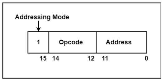
There are three parts of the Instruction Format, which are as follows:
Addressing Modes - Instructions that specify a particular memory location are known as memory-reference instructions. The method used to identify the target or effective address within the instruction is called the addressing mode.
The address field in an instruction can be represented in two ways:
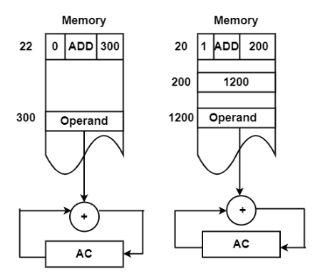
- Direct Addressing − It uses the actual address of the operand.
- Indirect Addressing − It uses an address that points to the operand.
The address of the operand or the target location is referred to as the effective address.
Effective Address (EA) − It refers to the address used as the target for a branch-type instruction or as the direct source of an operand for a computation-type instruction, without any intermediate changes.
Opcodes - An opcode is a set of bits that represents fundamental operations such as add, subtract, multiply, complement, and shift. The total number of operations supported by a computer determines how many bits are required for the opcode. To represent n operations, at least ⌈log₂n⌉ bits are needed. These operations are performed on data stored in processor registers or memory.
Address - The address refers to the location in memory where a particular instruction is stored. However, in some instructions, the address bits are treated as operands rather than actual memory addresses. In such cases, the instruction contains an immediate operand. If the second part includes a memory address, the instruction is said to use direct addressing.
Alternatively, if the second part includes the address of an operand, it is said to use indirect addressing. A single bit in the instruction code can indicate whether the address is direct or indirect.
The following figure illustrates direct and indirect addressing:
Examples: ADD R1, R2: This instruction adds the contents of register R1 to register R2. (Opcode: ADD, Operands: R1, R2)
LOAD R1, MEM_ADDR: This instruction loads data from memory location MEM_ADDR into register R1. (Opcode: LOAD, Operand: MEM_ADDR)
STORE R1, MEM_ADDR: This instruction stores data from register R1 into memory location MEM_ADDR. (Opcode: STORE, Operand: MEM_ADDR)
Computer Instructions
A computer stores programs in its RAM in the form of 1s and 0s, which the CPU interprets as instructions. One word of RAM contains one instruction in machine language.
These instructions are loaded into the CPU one at a time, where they are decoded and executed. A basic computer uses three instruction code formats: memory-reference instructions, register-reference instructions, and input-output instruction formats.
Memory-Reference Instruction - A memory-reference instruction uses 12 bits to specify an address and one bit to determine the addressing mode I. I is 0 for direct addressing and 1 for indirect addressing.

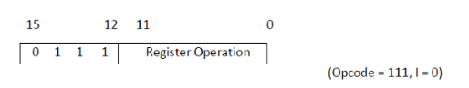
Register-Reference Instruction - Register-reference instructions are identified by the opcode 111 with a 0 in the leftmost bit (bit 15) of the instruction. These instructions perform operations or tests on the AC register. No memory operand is needed, as the remaining 12 bits specify the operation or test to be performed.
Input-Output Instruction - Input-output instructions do not require memory referencing and are identified by the opcode 111 with a 1 in the leftmost bit (bit 15) of the instruction. The remaining 12 bits specify the type of I/O operation or test.
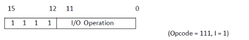
The type of instruction is identified by the control logic using the four bits in positions 12 through 15 of the instruction. If the three opcode bits (12–14) are not 111, the instruction is a memory-reference type, and bit 15 indicates the addressing mode.
If the 3-bit opcode is 111, the control unit checks bit 15: if it is 0, the instruction is a register-reference type; if it is 1, it is an input-output type.
Timing & Control
In computer architecture, timing and control refer to the mechanisms that coordinate the execution of instructions and the flow of data within the system. Timing signals synchronize component operations, while control signals direct data flow and instruct the CPU and other units on how to perform operations.
1. Timing Signals
Clock Signal: A master clock generator produces timing signals, typically as pulses or cycles, to synchronize operations.
Synchronized Operations: Timing signals ensure that different parts of the system, such as registers and flip-flops, operate in sync, allowing data to be processed at precise intervals.
Timing Unit: The timing unit generates various timing signals, often called T-states, which mark the start and end of different operations within a cycle.
2. Control Signals
Control Unit (CU): The CU generates control signals that direct data flow between components like the CPU, memory, and peripherals.
Instruction Execution: The CU interprets instructions and produces control signals to guide units such as the ALU in performing operations and storing results.
Data Flow: Control signals manage the movement of data between memory, registers, and the ALU, ensuring that the correct data is accessed and manipulated at the right time.
Hardwired vs. Microprogrammed: The CU may be implemented using hardwired logic (gates, flip-flops, etc.) or through microprogramming (storing a sequence of microinstructions in control memory).
3. Relationship to Instruction Cycle
Fetching, Decoding, and Execution: The control unit plays a key role in managing the instruction cycle—fetching instructions from memory, decoding them, reading operands if needed, and executing the instructions.
Micro-operations: The instruction cycle is broken down into micro-operations, which are individual steps. The CU generates the control signals required for each micro-operation.
Timing Diagrams: Timing diagrams visually represent the timing and control signals in the instruction cycle, showing how signals are generated and how they affect execution.
In essence, timing and control act as the engine that drives a computer’s operation. They ensure that instructions are executed in the correct order and that data flows between components in a coordinated manner, enabling the computer to function efficiently.
Instruction Cycles
A program stored in the memory unit of the computer consists of a series of instructions. The program is executed by the computer through a cycle for each instruction.
In a basic computer, each instruction cycle includes the following procedures:
- Fetching the instruction from memory.
- Decoding the instruction.
- Reading the effective address from memory if the instruction uses indirect addressing.
- Executing the instruction.
After these four procedures are completed, control returns to the first step and repeats the same process for the next instruction. Therefore, the cycle continues until a halt condition is encountered. The figure shows the phases involved in the instruction cycle.
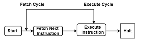
As shown in the figure, the halt condition occurs when the device is turned off, in the case of unrecoverable errors, or under similar circumstances.
Fetch Cycle
The address of the instruction to be executed is held in the program counter (PC). The processor fetches the instruction from the memory location pointed to by the PC.
Next, the PC is incremented to point to the address of the next instruction. The fetched instruction is loaded into the instruction register. The processor then decodes and performs the required operations.
Execute Cycle
Data transfer during execution takes place in two ways:
- Processor–Memory − Data is transferred either from the processor to memory or from memory to the processor.
- Processor–Input/Output − Data is transferred between the processor and a peripheral device.
In the execute cycle, the processor performs the required operations on the data, and control may modify the sequence of instruction execution. These two methods work together to complete the execute cycle.
State Diagram for Instruction Cycle
The figure below illustrates the detailed instruction cycle of a basic computer in the form of a state diagram. During an instruction cycle, some states may be skipped, while others may be visited multiple times.
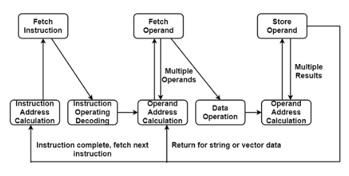
- Instruction Address Calculation − The address of the next instruction is computed by adding a fixed number to the address of the previous instruction.
- Instruction Fetch − The instruction is read from its memory location into the processor.
- Instruction Operation Decoding − The instruction is decoded to determine the type of operation to be performed and the operand(s) involved.
- Operand Address Calculation − The address of the operand is computed if it references memory or an I/O device.
- Operand Fetch − The operand is retrieved from memory or I/O.
- Data Operation − The operation specified by the instruction is executed.
- Store Operands − The result is stored in memory or sent to an I/O device.
Memory Reference Instruction
Memory reference instructions are commands that generate a reference to memory, allowing a program to access specified information and indicating where the data is continually cached. These instructions are known as Memory Reference Instructions.
There are seven memory reference instructions, which are as follows:
AND - The AND instruction performs a logical AND operation between the contents of a register and the memory word specified by the effective address. The result is stored back in the register.
ADD - The ADD instruction adds the contents of the memory word specified by the effective address to the value in the register.
LDA - The LDA instruction loads the memory word specified by the effective address into the register.
STA - The STA instruction stores the contents of the register into the memory location specified by the effective address. The output is then sent to the common bus, with the data input connected to the bus. This requires only one micro-operation.
BUN - The Branch Unconditionally (BUN) instruction changes the program control to the instruction located at the effective address. The Program Counter (PC), which holds the address of the next instruction to be executed, is updated to the new address. If the control needs to execute instructions that are not sequential, it can use the BUN instruction.
BSA - BSA stands for Branch and Save Return Address. This instruction allows the program to branch to a subroutine (a reusable block of code). When executed, BSA stores the return address (the next instruction's address) from the PC into the memory location specified by the effective address.
ISZ - The Increment and Skip if Zero (ISZ) instruction increments the word at the memory location specified by the effective address. If the result is zero, the PC is incremented by 1, effectively skipping the next instruction. A negative value can be stored in the memory word by the programmer, which may become zero after repeated increments, triggering the PC to skip the next instruction.
Example: A common MRI example is the "load" instruction, which reads data from a specific memory address and places it into a CPU register for further processing. For example, an instruction like "LOAD R1, 100" would load the value stored at memory address 100 into register R1.
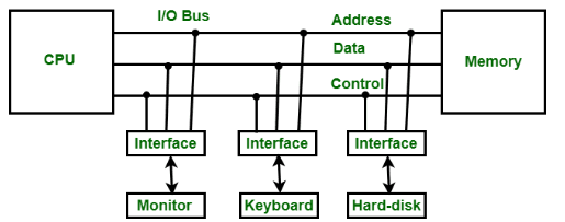
Input/Output & Interrupts
In computer architecture, input/output (I/O) refers to the process of sending data to and receiving data from external devices like keyboards, monitors, and printers. Interrupts are signals that allow devices to notify the CPU when an event occurs, such as a key press or data becoming available, without the CPU having to constantly check. This asynchronous communication improves efficiency by allowing the CPU to perform other tasks while waiting for I/O operations.
I/O and Interrupts: A Closer Look
-
I/O Devices: These are physical components that interact with the external environment, providing input (e.g., keyboard, mouse) and output (e.g., monitor, printer).
-
I/O Interfaces: These serve as bridges between the CPU and I/O devices, handling data transfer, signal conversion, and other necessary functions.
-
Interrupts: When an I/O device needs attention or has data ready, it sends an interrupt signal to the CPU.
-
Interrupt Service Routine (ISR): When an interrupt occurs, the CPU suspends its current task and executes a designated ISR to handle the event.
-
Efficiency: Interrupts make the system more efficient by freeing the CPU from constantly polling devices, allowing it to perform other tasks instead.
Types of Interrupts
- Hardware Interrupts: Triggered by external devices (e.g., button press, data received).
- Software Interrupts: Triggered by software (e.g., system calls).
- Non-Maskable Interrupts (NMIs): Critical events (e.g., power failure) that cannot be disabled.
Benefits of Interrupts
-
Improved Efficiency: CPU can handle other tasks while waiting for I/O operations.
-
Reduced Polling Overhead: Eliminates the need for continuous polling, saving CPU cycles.
-
Asynchronous Communication: Enables flexible and responsive interaction between CPU and I/O devices.
Complete Computer Description & Design of Basic Computer
A basic computer in computer architecture is a simplified model used to explain fundamental concepts of computer organization and design. It typically includes a memory unit, registers, a control unit, an arithmetic logic unit (ALU), and input/output devices, all connected through a common bus system.
A complete description of a computer includes its physical components, their functions, and how they interact to execute instructions and process data. This encompasses the instruction set architecture, instruction handling, and the hardware that implements them.
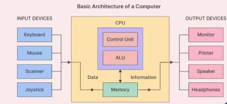
1. Functional Units:
-
Central Processing Unit (CPU): The "brain" of the computer, responsible for executing instructions and performing arithmetic and logic operations.
-
Memory: Stores data and instructions, including RAM (volatile) and storage devices like hard drives or SSDs (non-volatile).
-
Input/Output (I/O) Devices: Facilitate communication with the external environment (e.g., keyboard, monitor, printer).
-
Bus Systems: Connect components and transfer data and control signals.
2. Instruction Set Architecture (ISA):
-
Instructions: Commands the CPU can understand and execute.
-
Addressing Modes: Methods for specifying data locations (e.g., direct, indirect).
-
Data Types: Types of data handled by the CPU (e.g., integers, floats).
3. Computer Organization:
-
Microarchitecture: Internal CPU design, including instruction fetching, decoding, and execution.
-
Pipelining: Overlapping instruction execution to increase throughput.
-
Parallelism: Concurrent execution of multiple instructions to improve speed.
4. Control Unit:
-
Fetch-Decode-Execute Cycle: Retrieves instructions, decodes them, and executes them.
-
Control Signals: Direct the flow of data and operations within the CPU.
5. Input/Output:
-
I/O Interfaces: Hardware components that connect the system to external devices.
-
I/O Operations: The process of transferring data to/from external devices.
6. Memory System:
-
Main Memory (RAM): Provides fast access to actively used data and instructions.
-
Cache Memory: Small, high-speed memory for frequently accessed data.
-
Secondary Storage: Long-term storage for inactive data (e.g., HDD, SSD).
7. Basic Computer Components:
-
Registers: Small, fast storage within the CPU to hold data and instructions.
-
Arithmetic Logic Unit (ALU): Performs arithmetic and logical operations.
-
Bus: A pathway that facilitates communication among components.
8. Instruction Cycle:
- Fetch: Retrieve the next instruction from memory.
- Decode: Interpret the instruction.
- Execute: Carry out the instruction’s operation.
- Interrupt Cycle: Manage interrupts from I/O or other events.
9. Von Neumann Architecture:
- A computer architecture where data and instructions share the same memory space.
- Control Unit: Manages instruction execution.
- ALU: Handles arithmetic and logic operations.
The design of a basic computer involves understanding its core components and their interaction in executing instructions. These include the memory unit, registers, control unit, and a common bus. The memory stores data and instructions; registers temporarily hold data during processing; the control unit directs operations; and the bus transfers data among components.
Elaboration:
-
Memory Unit: Stores both data and instructions. Typically consists of 4096 words of 16 bits each.
-
Registers: Small, fast storage units inside the CPU. A basic computer has eight registers, including the Program Counter (PC), Instruction Register (IR), and Accumulator (AC).
-
Control Unit: Fetches, decodes, and executes instructions. Also coordinates data flow between memory and registers.
-
Common Bus System: A 16-bit data path used for transferring data between the memory, registers, and ALU.
-
Control Logic Gates and Flip-Flops: Implement the logic required for instruction decoding, execution, memory addressing, and data transfer.
-
Instruction Set: Defines operations for arithmetic, logic, data movement, and I/O handling.
-
Instruction Cycle: The CPU fetches, decodes, and executes instructions in a loop, forming the basis of program execution.
In essence, basic computer architecture offers a foundational understanding of how a computer works, serving as a stepping stone to more complex systems.