General Register Organization
When we use multiple general-purpose registers instead of a single accumulator register in CPU organization, this type of design is known as General Register-Based CPU Organization. In this type of organization, the computer uses two or three address fields in its instruction format. Each address field may specify either a general-purpose register or a memory word. If many CPU registers are available for heavily used variables and intermediate results, we can avoid memory references most of the time, thereby significantly increasing program execution speed and reducing program size.
For example:
MULT R1, R2, R3This is an arithmetic multiplication instruction written in assembly language. It uses three address fields: R1, R2, and R3. The meaning of this instruction is:
R1 ← R2 * R3This instruction can also be written using only two address fields as:
MULT R1, R2In this instruction, the destination register is the same as one of the source registers. This means the operation is:
R1 ← R1 * R2The use of a large number of registers results in shorter programs with fewer instructions.
Some examples of General Register-Based CPU Organizations are IBM 360 and PDP-11.
Features of a General Register-Based CPU Organization:
Registers: In this organization, the CPU contains a set of registers, which are small, high-speed memory locations used to store data being processed. The general-purpose registers can store any type of data, including integers, floating-point numbers, addresses, and control information.
Operand Access: The CPU accesses operands directly from the registers instead of loading them from memory each time. This significantly improves performance, as register access is much faster than memory access.
Data Processing: The CPU performs arithmetic and logical operations directly on the data stored in the registers. This eliminates the need to frequently transfer data between registers and memory, further enhancing performance.
Instruction Format: The instruction format typically includes fields for specifying the operands and the operation to be performed. The operands are identified by register numbers rather than memory addresses.
Context Switching: Context switching involves saving the contents of the registers to memory and restoring them when the process resumes. This is necessary to allow multiple processes to share the CPU.
Advantages of General Register-Based CPU Organization:
- CPU efficiency increases due to the use of a large number of registers.
- Programs occupy less memory, as instructions are more compact.
Disadvantages of General Register-Based CPU Organization:
- Care must be taken to avoid unnecessary register usage; thus, compilers need to be more intelligent.
- The use of many registers increases hardware cost.
Types of General Register CPU Organization:
1. Register-Memory Reference Architecture (CPU with fewer registers): In this organization, Source 1 is always required to be in a register, while Source 2 can be in either a register or memory. Two-address instruction formats are used.
2. Register-Register Reference Architecture (CPU with more registers): Here, ALU operations are performed only on data in registers. Operands must be in registers, and the result is also stored in a register. Three-address instruction formats are used.
Stack Organization
Stack is also known as the Last In First Out (LIFO) list. It is an important feature of the CPU. It stores data such that the element stored last is retrieved first. A stack is a memory unit with an address register. This register influences the address for the stack, which is known as the Stack Pointer (SP). The stack pointer continually determines the address of the element located at the top of the stack.
It can insert an element into or delete an element from the stack. The insertion operation is known as the push operation, and the deletion operation is known as the pop operation. In a computer stack, these operations are simulated by incrementing or decrementing the SP register.
Register Stack
The stack can be arranged as a set of memory words or registers. Consider a 64-word register stack arranged as shown in the figure. The stack pointer register holds a binary number, which is the address of the element present at the top of the stack. The three elements A, B, and C are located in the stack.
The element C is at the top of the stack, and the stack pointer holds the address of C, which is 3. The top element is popped from the stack by reading the memory word at address 3 and decrementing the stack pointer by 1. Then, B is at the top of the stack, and the SP holds the address of B, which is 2. To insert a new word, the stack is pushed by incrementing the stack pointer by 1 and inserting a word at that incremented location.
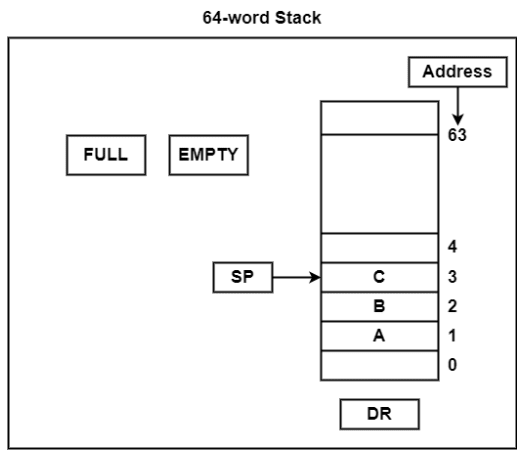
The stack pointer includes 6 bits because 2⁶ = 64, and the SP cannot exceed 63 (111111 in binary). If 63 is incremented by 1, the result is 0 (111111 + 1 = 1000000). SP holds only the six least significant bits. If 000000 is decremented by 1, the result is 111111.
Therefore, when the stack is full, the one-bit register ‘FULL’ is set to 1. If the stack is empty, then the one-bit register ‘EMTY’ is set to 1. The data register DR holds the binary information which is written into or read out of the stack.
Initially, the SP is set to 0, EMTY is set to 1, and FULL is set to 0. Now, as the stack is not full (FULL = 0), a new element is inserted using the push operation.
The push operation is executed as follows:
| Instruction | Description |
|---|---|
SP ← SP + 1 | It can increment stack pointer |
K[SP] ← DR | It can write element on top of the stack |
If (SP = 0) then (FULL ← 1) | Check if stack is full |
EMTY ← 0 | Mark the stack not empty |
The stack pointer is incremented by 1, and the address of the next higher word is saved in the SP. The word from DR is inserted into the stack using the memory write operation. The first element is saved at address 1, and the final element is saved at address 0. If the stack pointer is at 0, then the stack is full and ‘FULL’ is set to 1. This is the condition when the SP was at location 63, and after incrementing, the final element is saved at address 0. When an element is saved at address 0, there are no more empty registers in the stack. The stack is full, and ‘EMTY’ is set to 0.
An element is deleted from the stack if the stack is not empty (i.e., EMTY = 0). The pop operation includes the following sequence of micro-operations:
| Instruction | Description |
|---|---|
DR←K[SP] | It can read an element from the top of the stack |
SP ← SP - 1 | It can decrement the stack pointer |
If (SP = 0) then (EMTY ← 1) | Check if stack is empty |
FULL ← 0 | Mark the stack not full |
The top element from the stack is read and transferred to DR, and the stack pointer is decremented. If the stack pointer reaches 0, then the stack is empty and ‘EMTY’ is set to 1. This is the condition when the element in location 1 is read out and the SP is decremented by 1.
Instruction Format
An instruction includes a set of operation codes and operands that work with those operation codes. The instruction format defines the layout of bits in an instruction. It includes fields such as opcode, operands, and addressing mode.
Instruction length is typically maintained in multiples of the character length (8 bits). When instruction length is fixed, specific numbers of bits are assigned to opcode, operands, and addressing modes.
The bit allocation within an instruction depends on:
- Number of addressing modes
- Number of operands
- Number of CPU registers
- Number of register sets
- Number of address lines
The figure shows the general IA-32 (Intel Architecture - 32-bit) instruction format. IA-32 is used in many of Intel’s most prominent microprocessors. This format includes four fields: opcode field, addressing mode field, displacement field, and immediate field.

The opcode field has 1 or 2 bytes. The addressing mode field also has 1 or 2 bytes. If an instruction uses only one register to compute the effective address of an operand, the addressing mode field needs only one byte.
The displacement field follows the addressing mode field. If an effective address is computed using a displacement, this field may be 1 or 4 bytes. Immediate operands are placed in the immediate field, which also may be 1 or 4 bytes in size.
Types of Instructions
Based on the number of addresses, instructions are classified as:
Note: The expression X = (A + B) * (C + D) is used to demonstrate the procedure.
Zero Address Instructions
These instructions do not specify any operands or addresses. They operate on data implicitly, typically using a stack. For example, a zero-address instruction may add two values from the top of the stack without naming specific registers.

Stack-based computers do not use address fields in instructions. To evaluate an expression, it is first converted to Reverse Polish Notation (Postfix Notation).
Expression: X = (A + B) * (C + D)
Postfix   : X = AB+CD+*
TOP       : Top of stack
M[X] : Any memory location| Operation | Instruction | Stack (TOP Value After Execution) |
|---|---|---|
| Push A | PUSH A | TOP = A |
| Push B | PUSH B | TOP = B |
| Add | ADD | TOP = A + B |
| Push C | PUSH C | TOP = C |
| Push D | PUSH D | TOP = D |
| Add | ADD | TOP = C + D |
| Multiply | MUL | TOP = (C + D) * (A + B) |
| Pop X | POP X | M[X] = TOP |
One Address Instructions
These instructions specify one operand or address, which typically refers to a memory location or register. The instruction operates on the contents of that operand, and the result may be stored in the same or a different location. For example, a one-address instruction might load the contents of a memory location into a register.
This uses an implied ACCUMULATOR register for data manipulation. One operand is in the accumulator, and the other is in a register or memory location. "Implied" means that the CPU already knows that one operand is in the accumulator, so there is no need to specify it.
| opcode | operand/address of operand | mode |
|---|
Expression: X = (A+B)*(C+D)
AC is accumulator
M[] is any memory location
M[T] is temporary location| Operation | Instruction | Stack / Register (AC / M[]) |
|---|---|---|
| Load A | AC = A | AC = A |
| Add B | AC = AC + B | AC = A + B |
| Store M[T] | M[T] = AC | M[T] = A + B |
| Load C | AC = C | AC = C |
| Add D | AC = AC + D | AC = C + D |
| Store M[] | M[] = AC | M[] = C + D |
| Multiply M[T] | AC = AC * M[T] | AC = (A + B) * (C + D) |
Two Address Instructions
These instructions specify two operands or addresses, which may be memory locations or registers. The instruction operates on the contents of both operands, and the result may be stored in the same or a different location. For example, a two-address instruction might add the contents of two registers together and store the result in one of the registers.
This is common in commercial computers. Here, two addresses can be specified in the instruction. Unlike in one-address instructions where the result was stored in the accumulator, here the result can be stored in different locations rather than just in the accumulator. However, this requires more bits to represent the addresses.
| opcode | Destination address | Source address | mode |
|---|
Here, the destination address can also contain an operand.
Expression: X = (A+B)*(C+D)
R1, R2 are registers
M[] is any memory location| Operation | Instruction | Registers / Memory (R1, R2, M[]) |
|---|---|---|
| Load A | R1 = A | R1 = A |
| Add B | R1 = R1 + B | R1 = A + B |
| Store M[T] | M[T] = R1 | M[T] = A + B |
| Load C | R2 = C | R2 = C |
| Add D | R2 = R2 + D | R2 = C + D |
| Store M[] | M[] = R2 | M[] = C + D |
| Multiply M[T] | R1 = R1 * M[T] | R1 = (A + B) * (C + D) |
Three Address Instructions
These instructions specify three operands or addresses, which may be memory locations or registers. The instruction operates on the contents of all three operands, and the result may be stored in the same or a different location. For example, a three-address instruction might multiply the contents of two registers and add the contents of a third register, storing the result in a fourth register.
This format has three address fields to specify a register or a memory location. Programs created with this format are shorter in size, but the number of bits per instruction increases. These instructions make program creation easier, but it does not necessarily mean the program will run faster. Although the instructions contain more information, each micro-operation (changing the content of a register, loading an address into the address bus, etc.) is still performed in a single cycle.
| opcode | Destination address | Source address | Source address | mode |
|---|
Expression: X = (A+B)*(C+D)
R1, R2 are registers
M[] is any memory location| Operation | Instruction | Registers / Memory (R1, R2, M[]) |
|---|---|---|
| Load A | R1 = A | R1 = A |
| Add B | R1 = R1 + B | R1 = A + B |
| Store M[T] | M[T] = R1 | M[T] = A + B |
| Load C | R2 = C | R2 = C |
| Add D | R2 = R2 + D | R2 = C + D |
| Store M[] | M[] = R2 | M[] = C + D |
| Multiply M[T] | R1 = R1 * M[T] | R1 = (A + B) * (C + D) |
Addressing Modes
The operands of the instructions can be located either in main memory or in CPU registers. If the operand is placed in main memory, then the instruction provides the location address in the operand field. Many methods are used to specify the operand address. These different methods or modes for specifying operand addresses in instructions are known as addressing modes.
Types of Addressing Modes
There are various types of addressing modes, which are as follows:
Implied Mode − In this mode, the operands are specified implicitly in the definition of the instruction. For example, the instruction "complement accumulator" is an implied-mode instruction because the operand in the accumulator register is implied in the instruction. All register reference instructions that use an accumulator are implied-mode instructions.
Instruction format with mode field
| Opcode | Mode | Address |
|---|
Immediate Mode − In this mode, the operand is specified directly in the instruction itself. In other words, an immediate-mode instruction has an operand field instead of an address field. The operand field includes the actual value to be used in conjunction with the operation specified in the instruction. Immediate-mode instructions are useful for initializing registers with constant values.
Register Mode − In this mode, the operands are in registers within the CPU. A specific register is selected using a register field in the instruction. A k-bit field can identify any one of the 2^k registers.
Register Indirect Mode − In this mode, the instruction specifies a CPU register whose contents provide the address of the operand in memory. In other words, the selected register contains the address of the operand, not the operand itself.
A reference to the register is equivalent to specifying a memory address. The advantage of this mode is that the address field uses fewer bits to select a register than would be needed to directly specify a memory address.
Autoincrement or Autodecrement Mode − This is similar to register indirect mode, except that the register is incremented or decremented after (or before) its value is used to access memory. When the address in the register defines a table of data in memory, it is necessary to increment or decrement the register after every access. This can be done using increment or decrement operations.
Direct Address Mode − In this mode, the effective address is equal to the address part of the instruction. The operand resides in memory, and its address is provided directly in the instruction. In branch-type instructions, the address field specifies the actual branch address.
Indirect Address Mode − In this mode, the address field of the instruction specifies the memory location that holds the effective address. The CPU fetches the instruction and uses its address field to access memory again to retrieve the effective address.
Indexed Addressing Mode − In this mode, the contents of an index register are added to the address part of the instruction to obtain the effective address. The index register is a special CPU register that contains an index value. The address field of the instruction specifies the starting address of a data array in memory.
Data Transfer & Manipulation
In computer architecture, data transfer involves moving data between components like memory, registers, and I/O devices, while data manipulation refers to operations that alter the data, such as arithmetic, logical, or bitwise operations. These two concepts are fundamental to how computers process information and execute instructions.

Data Transfer:
Involves moving data without changing its content. This is essential for fetching instructions, storing results, and communication between system components.
Common Instructions: Load, store, move, exchange, input, output.
Examples:
- Load: Transfers data from memory to a processor register (e.g., LOAD R1, MEMORY_ADDRESS).
- Store: Transfers data from a processor register to memory (e.g., STORE R1, MEMORY_ADDRESS).
- Move: Transfers data between registers (e.g., MOVE R1, R2).
- Input/Output: Transfers data between the CPU and I/O devices (e.g., reading from a keyboard, writing to a display).
Data Manipulation:
Involves operations that modify data to achieve specific outcomes.
Common Operations:
- Arithmetic: Addition, subtraction, multiplication, division.
- Logical: AND, OR, XOR.
- Bitwise: Shift operations (left, right).
Examples:
- Add: ADD R1, R2 (adds the contents of R2 to R1).
- Logical AND: AND R1, R2 (performs a bitwise AND operation on R1 and R2).
- Shift Left: SHL R1, 2 (shifts the bits in R1 two positions to the left).
Program Control Instructions:
These alter the program’s execution flow based on conditions or results.
Common Instructions: Branch, jump, call, return.
Examples:
- Branch: Jumps to a different part of the code based on a condition (e.g., JMP IF_TRUE).
- Call: Transfers control to a subroutine and saves the return address.
- Return: Returns control to the caller after a subroutine is finished.
Program Control
Instructions for the computer are always stored in consecutive memory locations. These instructions are fetched from successive memory locations for processing and execution.
When an instruction is fetched from memory, the program counter is incremented by 1 so that it points to the address of the next consecutive instruction in memory. Once a data transfer or data manipulation instruction is executed, the program control, along with the program counter—which holds the address of the next instruction to be fetched—returns to the fetch cycle.
Data transfer and manipulation instructions specify the conditions for data processing operations, whereas program control instructions specify the conditions that can alter the content of the program counter.
Changes in the content of the program counter can cause an interrupt or break in instruction execution. However, program control instructions manage the flow of program execution and are capable of branching to different program segments.
Some of the program control instructions are listed in the table.
Program Control Instructions
| Name | Mnemonics |
|---|---|
| Branch | BR |
| Jump | JMP |
| Skip | SKP |
| Call | Call |
| Return | RET |
| Compare (by Subtraction) | CMP |
| Test (by ANDing) | TST |
The branch is a one-address instruction. It is represented as BR ADR, where ADR is a mnemonic for an address. The branch instruction transfers the value of ADR into the program counter. The terms "branch" and "jump" are often used interchangeably to mean the same; however, sometimes they denote different addressing modes.
Conditional branch instructions such as "branch if positive" or "branch if zero" specify the condition under which the flow of execution should be transferred. When the condition is met, the branch address is loaded into the program counter.
The figure below depicts conditional branch instructions.

The compare instruction performs an arithmetic subtraction. Here, the result of the operation is not saved; instead, the status bit conditions are set. The test instruction performs a logical AND operation on two operands and updates the status bits.
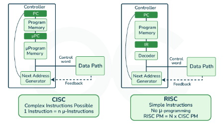
RISC
RISC is a design philosophy aimed at simplifying hardware, whereas CISC relies on single instructions that handle multiple tasks. In this article, we will discuss RISC and CISC in detail, along with their differences. Let's begin with RISC.
Reduced Instruction Set Computer (RISC)
The main idea behind RISC is to simplify hardware by using an instruction set composed of a few basic steps for loading, evaluating, and storing operations. For example, a load command loads data, and a store command stores data.
Characteristics of RISC
- Simpler instructions, hence simpler instruction decoding.
- Instructions typically fit within one word.
- Each instruction takes a single clock cycle to execute.
- More general-purpose registers.
- Simple addressing modes.
- Fewer data types.
- Pipelining can be implemented efficiently.
Advantages of RISC
- Simpler instructions: RISC processors use a smaller set of simple instructions, making them easier to decode and execute quickly, resulting in faster processing.
- Faster execution: Due to their simplicity, RISC instructions execute faster than those of CISC processors.
- Lower power consumption: RISC processors consume less power, making them ideal for portable devices.
Disadvantages of RISC
- More instructions required: RISC processors require more instructions to perform complex tasks compared to CISC processors.
- Increased memory usage: More instructions result in higher memory usage to store them.
- Higher cost: Developing and manufacturing RISC processors can be more expensive.
CISC
CISC stands for complex instruction set computer. The core idea behind CISC is that a single instruction performs loading, evaluating, and storing operations. For example, a multiplication command can load data, process it, and store the result, making the instruction complex.
Characteristics of CISC
- Complex instructions, hence complex instruction decoding.
- Instructions are larger than one word.
- Instructions may take more than one clock cycle to execute.
- Fewer general-purpose registers, as operations are performed directly in memory.
- Complex addressing modes.
- More data types supported.
Advantages of CISC
- Reduced code size: Complex instructions can perform multiple operations, reducing the number of instructions needed.
- More memory efficient: Fewer instructions are needed for complex tasks, resulting in more compact code.
- Widespread use: CISC processors have been around longer, with broader software and developer support.
Disadvantages of CISC
-
Slower execution: Complex instructions take longer to decode and execute.
-
More complex design: The instruction set is harder to implement and optimize.
-
Higher power consumption: More complex instructions result in greater power usage.
CPU Performance
Both approaches aim to improve CPU performance:
-
RISC: Reduces the number of cycles per instruction at the cost of increasing the number of instructions per program.
-
CISC: Minimizes the number of instructions per program but increases the number of cycles per instruction. In earlier times, when programming was done using assembly language, it was beneficial for instructions to handle more tasks due to the tedious and error-prone nature of assembly programming. This led to the development of CISC. However, with the rise of high-level languages and reduced dependency on assembly, RISC architecture gained popularity.
Example:
Suppose we have to add two 8-bit numbers:
- CISC approach: A single command like
ADDperforms the entire task. - RISC approach: The programmer writes a
loadcommand to move data into registers, uses an appropriate operator to perform the addition, and then stores the result.
Thus, the add operation is divided into parts—load, operate, and store. As a result, RISC programs are longer and require more memory to store but use fewer transistors due to the simplicity of instructions.
| CISC | RISC |
|---|---|
| The original microprocessor ISA | Redesigned ISA that emerged in the early 1980s |
| Instructions can take several clock cycles | Single-cycle instructions |
| Hardware-centric design | Software-centric design |
| The ISA does as much as possible using hardware circuitry | High-level compilers take on most of the burden of coding many software steps from the programmer |
| More efficient use of RAM than RISC | Heavy use of RAM (can cause bottlenecks if RAM is limited) |
| Complex and variable length instructions | Simple, standardized instructions |
| May support microcode (micro-programming where instructions are treated like small programs) | Only one layer of instructions |
| Large number of instructions | Small number of fixed-length instructions |
| Compound addressing modes | Limited addressing modes |