Peripheral Devices
A peripheral device is any external device connected to a computer that adds functionality but is not part of the core computer system. These devices typically handle input, output, or both, and are also known as input-output (I/O) devices. While not essential for a computer to perform its basic operations, peripherals enhance the user’s experience by expanding the system’s capabilities. Common examples include keyboards, mice, printers, and external drives. Although the term is sometimes used loosely, it generally refers to devices located outside the computer case.
Classification of Peripheral Devices
Peripheral devices are generally classified into four basic categories:
1. Input Devices: An input device is defined as a device that converts incoming data and instructions into a pattern of electrical signals in binary code that are comprehensible to a digital computer.
- Keyboard: An input device that allows users to enter text and commands into a computer system.
- Mouse: An input device that allows users to control the cursor on a computer screen.
- Scanner: An input device that converts physical documents and images into digital files.
- Microphone: An input device that records audio.
2. Output Devices: An output device performs the reverse of the input process by translating digitized signals into a form intelligible to the user. It also facilitates the transfer of data from one computer system to another. At one time, punched cards and paper tape readers were used extensively for input, but these have now been replaced by more efficient devices.
Examples:
- Monitor: An output device that displays visual information from a computer system.
- Printer: An output device that produces physical copies of documents or images.
- Speaker: An output device that produces audio.
3. Storage Devices: Storage devices are used to store data required for performing operations in the system. They are essential for data retention and system functionality and offer better compatibility.
Examples:
- Hard Drive: Stores data and files on a computer system.
- USB Drive: A small, portable storage device that provides additional storage space.
- Memory Card: A compact storage device commonly used in digital cameras and smartphones.
- External Hard Drive: A portable storage device that connects to a computer to provide additional space.
4. Communication Devices: Communication devices are hardware components that enable data exchange between computer systems or networks.
Examples:
- Modem: Connects a computer system to the internet.
- Network Card: Connects a computer system to a network.
- Router: Allows multiple devices to connect to a network.
Peripheral devices are important for enhancing the functionality of a computer. Here's why they are so important:
- Enhanced Functionality: They expand a computer's capabilities, enabling it to perform various tasks.
- User Interaction: Input devices like keyboards and mice allow users to interact with the system.
- Data Output: Output devices such as monitors and printers present processed data.
- Data Storage: Storage devices ensure important data is saved and accessible.
- Communication: Communication devices enable network connectivity and data exchange.
- Increased Efficiency: They improve the overall efficiency and usability of the computer by adding specialized functions.
Peripheral devices can connect to a computer through various methods, each offering different speeds, ranges, and compatibility. Common connection options include:
- USB: Common for keyboards, mice, printers, and external storage; supports wired and wireless connections.
- Bluetooth: A wireless connection used for devices like headphones, speakers, and mice.
- Wi-Fi: Used for wireless networked devices like printers and cameras.
- HDMI: Connects monitors, projectors, and TVs for high-definition video and audio.
- Ethernet: A wired connection for network communication, typically used for internet or LAN access.
- Thunderbolt: A high-speed connection for external devices like storage drives and monitors.
- VGA: An older connection standard for monitors or projectors; supports lower video resolutions.
- DisplayPort: Similar to HDMI, used for connecting high-definition monitors.
I/O Interface
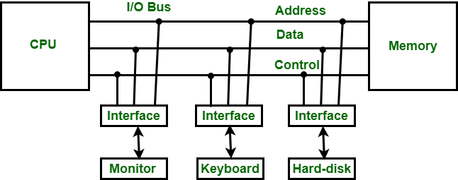
The Input-Output (I/O) interface is a method that facilitates the transfer of information between internal storage devices (i.e., memory) and external peripheral devices. A peripheral device provides input to or receives output from the computer and is also called an Input-Output device. For example: A keyboard and mouse, which provide input to the computer, are input devices, while a monitor and printer, which provide output, are output devices. Similarly, external hard drives and other peripherals may provide both input and output.
In a microcomputer-based system, the main purpose of peripheral devices is to establish special communication links for interfacing with the CPU. To address the differences between peripheral devices and the CPU, communication links are necessary.
The major differences are as follows:
- The nature of peripheral devices is electromagnetic or electromechanical, whereas the CPU is electronic. Their modes of operation differ significantly.
- A synchronization mechanism is required because the data transfer rate of peripheral devices is slower than that of the CPU.
- The data codes and formats in peripheral devices differ from those in the CPU and memory.
- The operating modes of peripheral devices differ, and each must be controlled in a way that doesn't interfere with the operation of others connected to the CPU.
- Additional hardware is needed to resolve these differences, supervise, and synchronize all input and output operations.
Functions of Input-Output Interface:
- Synchronizes the operating speed of the CPU with I/O devices.
- Selects the appropriate I/O device for signal interpretation.
- Provides control and timing signals.
- Buffers data through the data bus.
- Detects various types of errors.
- Converts serial data into parallel and vice versa.
- Converts digital data into analog signals and vice versa.
Modes of Data Transfer
Modes of data transfer in Computer Organization and Architecture (COA) refer to the different methods by which data is exchanged between the central processing unit (CPU) and peripheral devices. These modes manage data flow within a computer system. Although the CPU processes the data, the source and destination are typically the memory unit. Data can be transferred using three modes:
- Programmed I/O
- Interrupt-Initiated I/O
- Direct Memory Access (DMA)
Programmed I/O
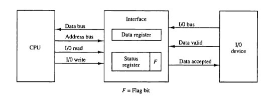
Programmed I/O operations result from I/O instructions written in the program. Each data item transfer is initiated by an instruction and usually involves moving data between a CPU register and a peripheral device. Additional instructions are needed for transferring data between the CPU and memory.
This mode requires constant monitoring of the peripheral by the CPU. After initiating a transfer, the CPU must monitor the interface to determine when the next transfer can occur. The CPU executes instructions to monitor the interface unit and the I/O device.
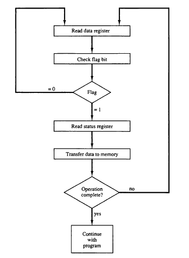
Data Transfer from I/O Device to CPU
Flow-Chart for CPU Program to Input Data
Examples:
- Reading data from a keyboard or mouse, where the CPU continuously polls for input.
- Writing data to a printer, where the CPU initiates the operation, checks status, and sends data in small chunks.
To execute an I/O instruction, the processor issues an address identifying the I/O module and device, along with an I/O command. There are four types of I/O commands:
- Control: Activates a peripheral and instructs it. For example, instructing a tape unit to rewind.
- Test: Checks the status of an I/O module and its peripheral. The CPU verifies if the device is powered, ready, or has encountered an error.
- Read: The I/O module gets data from the peripheral and places it in an internal buffer. The CPU then reads it via the data bus.
- Write: The I/O module takes data from the data bus and sends it to the peripheral.
Advantages:
- Simple to implement
- Minimal hardware required
Disadvantages:
- Busy-waiting
- CPU is tied up and cannot perform other tasks
Interrupt-Initiated I/O
This mode uses an interrupt facility and special commands to inform the interface to issue the interrupt command when data becomes available and the interface is ready for data transfer. In the meantime, the CPU keeps executing other tasks and does not need to check the flag. When the flag is set, the interface is informed and an interrupt is initiated. This interrupt causes the CPU to deviate from what it is doing to respond to the I/O transfer. The CPU responds to the signal by storing the return address from the program counter (PC) into the memory stack and then branches to a service that processes the I/O request. After the transfer is complete, the CPU returns to the previous task it was executing. The branch address of the service can be chosen in two ways, known as vectored and non-vectored interrupts. In a vectored interrupt, the source that interrupts supplies the branch information to the CPU, while in the case of a non-vectored interrupt, the branch address is assigned to a fixed location in memory.
Interrupt-initiated I/O, also referred to as hard-initiated I/O, is where input and output operations are performed when an interrupt signal is detected by the CPU.
Interrupt-initiated I/O is a more efficient approach, as the I/O device sends a signal to the CPU indicating it is ready for data transfer. The CPU performs other tasks until it receives an interrupt request.
Working of CPU in terms of interrupts:
- The CPU issues a read command.
- It starts executing other programs.
- It checks for interruptions at the end of each instruction cycle.
- On interruption: It processes the interrupt by fetching data and storing it.
- It resumes working on the program it was executing.
Advantages
- Reduced overhead on the CPU, as it waits for an interrupt while performing other tasks simultaneously.
- No need to monitor the status of a specific device continuously.
- Reduces CPU time wastage, hence enhancing system performance.
Disadvantages
- Difficult to implement and program compared to sequential file processing, especially when implemented in low-level languages.
- Requires interrupt handling routines, which can be time-consuming.
DMA Transfer
In modern computer systems, transferring data between input/output devices and memory can be a slow process if the CPU is required to manage every step. To address this, a Direct Memory Access (DMA) Controller is utilized.
A Direct Memory Access (DMA) Controller solves this by allowing I/O devices to transfer data directly to memory, reducing CPU involvement. This increases system efficiency and speeds up data transfers, freeing the CPU to focus on other tasks. The DMA controller requires the same basic circuits of an interface to communicate with the CPU and input/output devices.
DMA uses hardware for accessing the memory. This hardware is called a DMA Controller. Its job is to transfer data between input/output devices and main memory with very little interaction with the processor. The Direct Memory Access Controller is a control unit that manages data transfers.
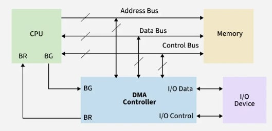
Architecture
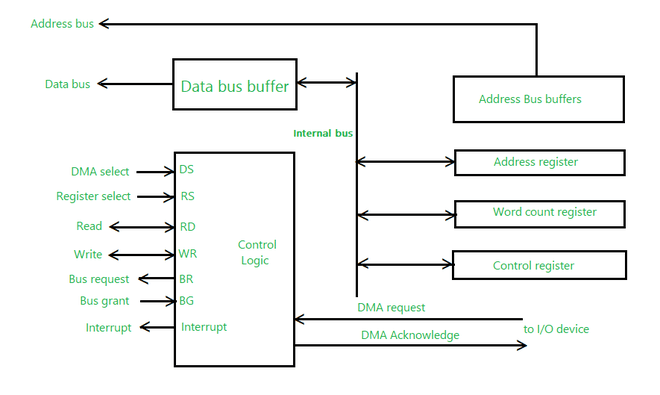
The DMA Controller is a type of control unit that acts as an interface between the data bus and I/O devices. As mentioned, the DMA Controller transfers data without processor intervention, although the processor can control data transfer. The DMA Controller also contains an address unit, which generates addresses and selects I/O devices for data transfer. Below is the block diagram of the DMA Controller.
Types There are four popular types of DMA:
- Single-Ended DMA: In this type, the DMA controller is connected only to one device (usually either the memory or the I/O device) and directly controls data transfer.
- Dual-Ended DMA: The DMA controller is connected to both the source and the destination, typically memory and an I/O device.
- Arbitrated-Ended DMA: In systems with multiple DMA devices or masters, arbitration is needed to decide which device gets control of the bus. It is more advanced than Dual-Ended DMA.
- Interleaved DMA: Interleaved DMA refers to DMA that reads from one memory address and writes to another memory address.
Working The DMA controller contains three main registers:
- Address register: Contains the address to specify the desired location in memory.
- Word count register: Contains the number of words to be transferred.
- Control register: Specifies the transfer mode.
All registers in the DMA appear to the CPU as I/O interface registers. Therefore, the CPU can both read and write to the DMA registers under program control via the data bus.
The figure below shows the block diagram of the DMA controller. The unit communicates with the CPU through the data bus and control lines. Through the use of the address bus and by allowing the DMA and RS register to select inputs, the register within the DMA is chosen by the CPU.
RD and WR are two-way inputs. When the BG (bus grant) input is 0, the CPU can communicate with DMA registers. When the BG (bus grant) input is 1, the CPU has relinquished the buses and the DMA can communicate directly with the memory.
The CPU initializes the DMA by sending the following information through the data bus:
- The starting address of the memory block where the data is available (to read) or where data is to be stored (to write).
- The word count, which is the number of words in the memory block to be read or written.
- A control signal to define the mode of transfer such as read or write.
- A control signal to begin the DMA transfer.
Modes of Data Transfer in DMA
There are three modes of data transfer in DMA, described below.
Burst Mode
- In Burst Mode, the DMA controller takes full control of the system bus and transfers the entire block of data in one go.
- The bus is not handed back to the CPU until the entire data transfer is complete.
- This mode is efficient for large data transfers but can delay CPU operations.
Transparent Mode
- In Transparent Mode, the DMA controller transfers data only when the CPU is not using the system bus.
- It effectively performs transfers during idle CPU cycles, ensuring the CPU is never interrupted.
- Best when CPU performance is critical and some delay in data transfer is acceptable.
Cycle Stealing Mode
- In Cycle Stealing Mode, the DMA controller transfers one byte (or word) at a time and then releases control of the bus back to the CPU.
- This mode generates frequent bus requests but allows the CPU to execute instructions in between DMA transfers.
- Useful when the DMA task is important but should not entirely block the CPU, such as in audio or video streaming.
Advantages of DMA Controller
- DMA speeds up memory operations and data transfers by allowing peripherals to communicate directly with memory, bypassing the CPU.
- During data transfer, the CPU is not involved, which significantly reduces its workload.
- Operates efficiently, requiring very few clock cycles to complete data transfers.
- Distributes workload effectively.
- By offloading data movement tasks from the CPU, DMA balances the overall system workload more efficiently.
Disadvantages of DMA Controller
- Costly operation due to the need for additional hardware and control logic.
- Suffers from cache-coherence problems.
- Increases the overall cost of the system.
- Increases the complexity of the software.
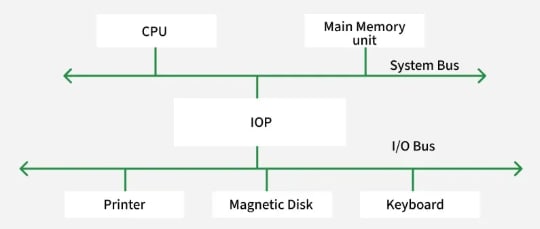
I/O Processor
The DMA mode of data transfer reduces the CPU's overhead when handling I/O operations. It also allows parallel processing between the CPU and I/O operations. This parallelism is necessary to avoid the wastage of valuable CPU time when handling I/O devices whose speeds are much slower compared to the CPU. The concept of DMA operation can be extended to further relieve the CPU from getting involved in the execution of I/O operations. This led to the development of special-purpose processors called Input-Output Processors (IOPs) or I/O channels.
The Input-Output Processor (IOP) is similar to a CPU that handles the details of I/O operations. It is more capable than a typical DMA controller. The IOP can fetch and execute its own instructions that are specifically designed to manage I/O transfers. In addition to I/O tasks, it can also perform other processing tasks like arithmetic, logic, branching, and code translation. The main memory unit plays a pivotal role and communicates with the processor via DMA.
Working The Input-Output Processor is a specialized processor that loads and stores data in memory along with executing I/O instructions. It serves as an interface between the system and devices. It follows the sequence of steps below to perform I/O operations and store the results in memory:
- The I/O processor is triggered by a request from the system or a peripheral device to initiate an I/O operation.
- It fetches instructions specifically designed for I/O transfers from its own instruction set.
- Memory space is allocated in the main memory to hold the data being transferred.
- Direct Memory Access (DMA) is used to transfer data directly between the I/O device and memory, bypassing the CPU.
- Data is buffered temporarily between the I/O device and memory to ensure efficient processing.
- I/O commands, such as read, write, or synchronize, are executed to control the data transfer process.
- If errors occur, interrupts are handled and error corrections are managed independently.
- Once the data transfer is complete, the results are stored in memory, and the operation is marked as complete.
- The system or peripheral device is informed that the I/O operation has been completed and the results are available.
- After the I/O operation, control of the resources is released, and the CPU resumes processing other tasks.
Features
- An IOP is equipped with specialized hardware that is optimized for handling input/output operations. This hardware includes input/output ports, DMA controllers, and interrupt controllers.
- It has the capability to perform Direct Memory Access (DMA) operations. DMA allows data to be transferred directly between peripheral devices and memory without going through the CPU, thereby freeing up the CPU for other tasks.
- It can handle interrupts from peripheral devices and manage them independently of the CPU. This allows the CPU to focus on executing application programs while the IOP handles interrupts.
- It can handle communication protocols (Ethernet, USB, SCSI) to interface with devices, reducing the need for CPU intervention.
- It can buffer data between the CPU and peripherals to prevent overload and improve data handling.
- It can process commands from peripheral devices independently of the CPU. This allows the CPU to focus on executing application program tasks.
- It can perform input/output operations in parallel with the CPU. This enables the system to handle multiple tasks simultaneously and improve overall system performance.
Applications
- I/O processors can be used in data acquisition systems to handle real-time data transfer and processing.
- They can be used in industrial control systems for precise timing, control signals, and local data processing.
- They can handle multimedia I/O, including real-time data processing for audio, video, and compression.
- They can process network data, including routing, filtering, and encryption.
- They can handle high-speed data transfers, caching, and prefetching for storage systems.
Advantages
- The I/O devices can directly access the main memory without the intervention of the processor in I/O processor-based systems.
- With an I/O processor, the main processor doesn't have to deal with I/O operations, allowing it to focus on other tasks. This results in more efficient use of the processor's resources and can lead to faster overall system performance.
- Since the I/O processor can access memory directly, data transfers between I/O devices and memory can be faster and more efficient than with other methods.
- By offloading I/O tasks to a dedicated processor, the system can be made more fault-tolerant. For example, if an I/O operation fails, it won't affect other system processes.
Disadvantages
- I/O processors can add significant costs to a system due to the additional hardware and complexity required. This can be a barrier to adoption, especially for smaller systems.
- The addition of an I/O processor can increase the overall complexity of a system, making it more difficult to design, build, and maintain. This can also make it harder to diagnose and troubleshoot issues.
- While I/O processors can improve system performance by offloading I/O tasks from the main processor, the gains may not be significant in all cases. In some cases, the additional overhead of the I/O processor may actually slow down the system.
- With multiple processors accessing the same memory, synchronization issues can arise, leading to potential data corruption or other errors.
Serial Communication
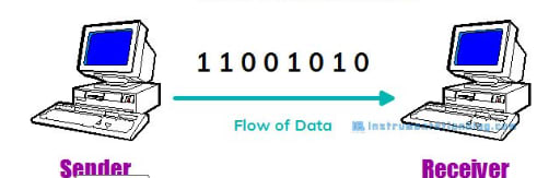
Serial communication is a communication method that uses one or two transmission lines to send or receive data, one bit at a time. In general, communication is the method of interchange of information between individuals.
Every device, such as your personal computer or smartphone, runs on a serial protocol. The protocol is a secure and reliable form of communication. This is the simplest form of communication between a sender and a receiver.
Several different standards such as RS232, RS422, RS485, etc., are well-known examples of serial communication.
Types of Transmission Modes In serial communication, data is transferred in the form of binary pulses. The transmission modes are classified as Simplex, Half Duplex, and Full Duplex.
Simplex Method
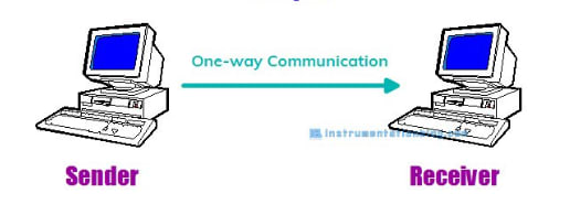
This method is a unidirectional or one-way communication method. Only one of the two devices on a link can transmit the data; the other can only receive.
If a sender transmits, then the receiver can only receive the data. Typical examples of this communication method are Radio and Television.
Half Duplex Method
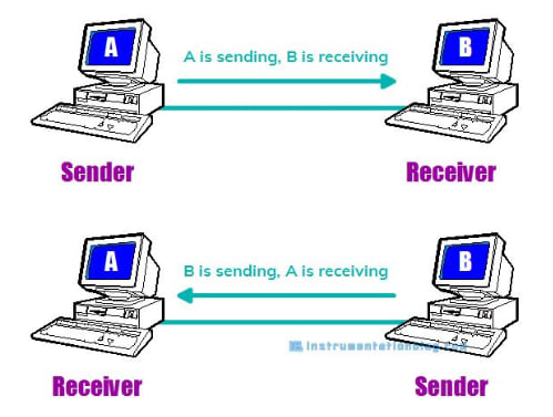
In the Half Duplex method, both the sender and receiver can transmit the data but not at the same time. When one is sending the data, the other can only receive, and vice versa.
This method is popular among those devices where there is no need for communication in both directions at the same time.
A Walkie-Talkie is the best example of the half-duplex method. Another good example is the internet; if a client (laptop) sends a request for a web page, the web server processes the application and sends back the information.
Full Duplex Method
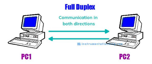
In the Full Duplex method, both the sender and receiver can transmit and receive data simultaneously.
The Full Duplex method is used when communication in both directions is required all the time. A smartphone is an example of a full-duplex communication device.
Types of Data Transmission
Data transmission can happen in two ways: Serial Communication and Parallel Communication.
Serial communication is a technique in which data is sent bit by bit using two wires, while parallel communication moves 8, 16, or 32 bits of data at a time.
Difference between Serial and Parallel Communication
In serial communication, one bit flows at one clock pulse. So, there are fewer input-output lines. Hence, it occupies less space and has more resistance to cross-talk. The cost of the entire system becomes low and is generally preferred for long-distance communication.
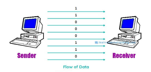
In parallel communication, many bits (8, 16, or 32 bits) flow together simultaneously at a time. So, each bit of data requires separate physical input-output lines. The advantage of parallel communication is its speed, but its drawback is that it uses more input-output lines.
Clock Synchronization In order to work efficiently with serial devices, the clock is the primary source. The clock signal for each serial device is different, and it is categorized as synchronous transmission and asynchronous transmission.
Synchronous Transmission
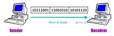
In Synchronous Transmission, data is sent in the form of blocks or frames. This transmission is of the full-duplex type. Synchronization between the sender and receiver is compulsory.
In synchronous transmission, there is no gap between data. It is more efficient and reliable than asynchronous transmission for transferring a large amount of data.
Asynchronous Transmission
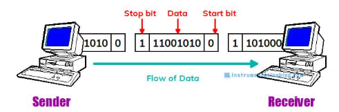
In Asynchronous Transmission, data is sent in the form of bytes or characters. This transmission is of the half-duplex type.
In this transmission, start bits and stop bits are added with data. It does not require synchronization.
Parameters for Serial Communication
-
Baud Rate Baud rate is the rate at which information is transferred from a sender to a receiver. Its unit is bits per second. Some of the standard baud rates are 1200, 2400, 4800, 9600, and 57600. The user has to set the baud rate on both the sender and receiver sides.
-
Framing Framing is a group of data bits that the user wants to send from a sender to a receiver. Usually, 8 bits are preferred.
-
Synchronization There are 1 start bit and 1 or 2 stop bits in the framing from the transmitter's end. The start bit indicates the beginning of data transfer, and the stop bit indicates the end of the data transfer to the receiver. This process is also known as asynchronous data transfer.
-
Error Control This is a function to detect errors in the data and is selected from “even parity check (EVEN),” “odd parity check (ODD),” or “no parity check (NONE).”
Central Processing Unit
General register organization, stack organization, instruction format, addressing modes, data transfer & manipulation, program control, RISC, CISC.
Computer Arithmetic
Unsigned, signed and floating-point data representation, addition, subtraction, multiplication and division algorithms. Booth's multiplication algorithm.