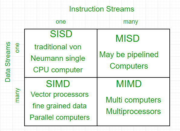
Flynn's classification
Parallel computing is a computing technique where jobs are broken into discrete parts that can be executed concurrently. Each part is further broken down into a series of instructions. Instructions from each part execute simultaneously on different CPUs. Parallel systems deal with the simultaneous use of multiple computer resources, which can include a single computer with multiple processors, a number of computers connected by a network to form a parallel processing cluster, or a combination of both. Parallel systems are more difficult to program than computers with a single processor because the architecture of parallel computers varies accordingly, and the processes of multiple CPUs must be coordinated and synchronized. The crux of parallel processing is the CPUs. Based on the number of instruction and data streams that can be processed simultaneously, computing systems are classified into four major categories:
Flynn's classification
1. Single-instruction, single-data (SISD) systems – An SISD computing system is a uniprocessor machine that is capable of executing a single instruction, operating on a single data stream. In SISD, machine instructions are processed in a sequential manner, and computers adopting this model are popularly called sequential computers. Most conventional computers have SISD architecture. All the instructions and data to be processed have to be stored in primary memory.
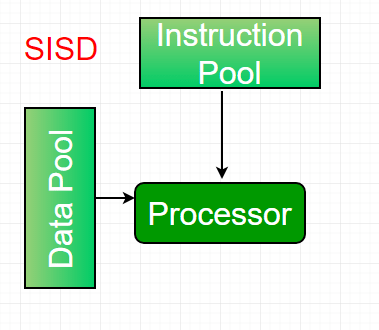
The speed of the processing element in the SISD model is dependent on the rate at which the computer can transfer information internally. Dominant representative SISD systems are IBM PCs and workstations.
2. Single-instruction, multiple-data (SIMD) systems – An SIMD system is a multiprocessor machine capable of executing the same instruction on all the CPUs but operating on different data streams. Machines based on the SIMD model are well suited for scientific computing since they involve lots of vector and matrix operations. To allow information to be passed to all the processing elements (PEs), organized data elements of vectors can be divided into multiple sets (N-sets for N PE systems), and each PE can process one data set.
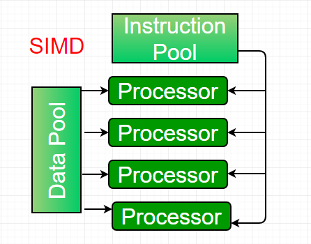
A dominant representative SIMD system is Cray’s vector processing machine.
3. Multiple-instruction, single-data (MISD) systems – An MISD computing system is a multiprocessor machine capable of executing different instructions on different PEs, but all of them operate on the same data set.
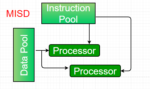
Example: Z = sin(x) + cos(x) + tan(x). The system performs different operations on the same data set. Machines built using the MISD model are not useful for most applications; a few machines have been built, but none are available commercially.
4. Multiple-instruction, multiple-data (MIMD) systems – An MIMD system is a multiprocessor machine capable of executing multiple instructions on multiple data sets. Each PE in the MIMD model has separate instruction and data streams; therefore, machines built using this model are capable of running any kind of application. Unlike SIMD and MISD machines, PEs in MIMD machines work asynchronously.
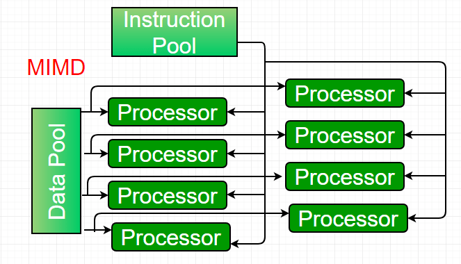
MIMD machines are broadly categorized into shared-memory MIMD and distributed-memory MIMD, based on the way PEs are coupled to the main memory. In the shared-memory MIMD model (tightly coupled multiprocessor systems), all the PEs are connected to a single global memory and all have access to it. Communication between PEs in this model takes place through the shared memory; modification of the data stored in the global memory by one PE is visible to all other PEs. Dominant representative shared-memory MIMD systems are Silicon Graphics machines and Sun/IBM’s SMP (Symmetric Multi-Processing).
In distributed-memory MIMD machines (loosely coupled multiprocessor systems), all PEs have local memory. Communication between PEs in this model takes place through the interconnection network (the inter-process communication channel, or IPC). The network connecting PEs can be configured as a tree, mesh, or in accordance with the requirement. The shared-memory MIMD architecture is easier to program but is less tolerant to failures and harder to scale compared to the distributed-memory MIMD model. Failures in a shared-memory MIMD system affect the entire system, whereas this is not the case in the distributed model, in which each PE can be easily isolated. Moreover, shared-memory MIMD architectures are less likely to scale because adding more PEs leads to memory contention—a situation that does not occur in the distributed memory model, where each PE has its own memory. As a result of practical outcomes and user requirements, distributed-memory MIMD architecture is superior to the other existing models.
Pipelining
Pipelining defines the temporal overlapping of processing. Pipelines are similar to assembly lines in computing and can be used either for instruction processing or, more generally, for executing any complex operations. It can be used efficiently only for a sequence of similar tasks, much like assembly lines.
A basic pipeline processes a sequence of tasks, including instructions, according to the following principle of operation:
Each task is subdivided into multiple successive subtasks, as shown in the figure. For instance, the execution of register-register instructions can be broken down into instruction fetch, decode, execute, and writeback.
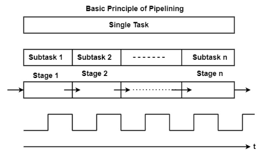
A pipeline phase corresponding to each subtask executes the necessary operations.
A similar amount of time is allocated in each stage for executing the required subtask.
All pipeline stages work just like an assembly line, receiving their input from the previous stage and transferring their output to the next stage.
Finally, the basic pipeline operates in a clocked, or synchronous, manner. This means that each stage receives a new input at the beginning of the clock cycle, has a single clock cycle available to execute the required operations, and produces the result for the next stage by the beginning of the subsequent clock cycle.
Advantages
- The cycle time of the processor is decreased, improving instruction throughput. Pipelining does not lower the time it takes to execute an individual instruction; rather, it increases the number of instructions that can be processed concurrently ("at once") and reduces the delay between completed instructions (known as 'throughput').
- When pipelining is used, the CPU Arithmetic Logic Unit (ALU) can be designed to be faster, although more complex.
- Pipelining increases execution speed over an unpipelined core by a factor of the number of stages (assuming the clock frequency also increases by a similar factor), and the code is optimized for pipeline execution.
- Pipelined CPUs frequently operate at a higher clock frequency than the RAM clock frequency (as of 2008 technologies, RAM operates at a lower frequency compared to CPU frequencies), increasing the computer’s overall performance.
Pipeline organization is generally applicable to two areas of computer design:
1. Instruction Pipeline – An instruction pipeline fetches sequential instructions from memory while prior instructions are being executed in other portions of the processor. Pipeline processing can be seen in both the data and instruction streams.
2. Arithmetic Pipeline – An arithmetic pipeline divides a given arithmetic problem into subproblems that can be executed in different pipeline segments. It is used for multiplication, floating-point operations, and various other calculations.
Arithmetic Pipeline
Arithmetic pipelines are commonly used in various high-performance computers. They are used to implement floating-point operations, fixed-point multiplication, and other similar types of calculations that arise in scientific applications.
Let’s look at an example to better understand the concept of an arithmetic pipeline. Here, we perform addition and subtraction of floating-point numbers on a unit of the pipeline.
The inputs in the floating-point adder pipeline refer to two different normalized floating-point binary numbers, defined as follows:
A = X * 2ˣ = 0.9504 * 10³
B = Y * 2ʸ = 0.8200 * 10²
Where x and y refer to the exponents, and X and Y refer to two fractions representing the mantissa.
The floating-point addition and subtraction process is broken into four stages. The corresponding sub-operation to be executed in the specified pipeline is contained in each stage. The four stages perform the following sub-operations:
- Comparing the exponents using subtraction
- Aligning the mantissa
- Adding or subtracting the mantissa
- Normalizing the result
Later in this section, we’ll go through each sub-operation in greater detail. The sub-operations performed in each pipeline stage are depicted in the block diagram below:
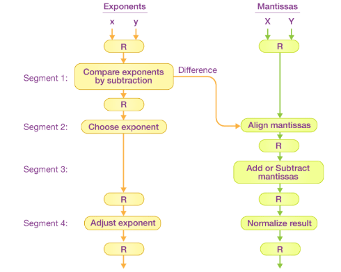
Note: Registers are placed after every sub-operation to store the intermediate results.
1. Comparing Exponents by Subtraction - The difference between the exponents is calculated by subtracting them. The exponent of the result is chosen to be the larger exponent.
The exponent difference, 3 – 2 = 1, defines the number of times the mantissa associated with the smaller exponent should be shifted to the right.
2. Aligning the Mantissa - Based on the exponent difference calculated in stage one, the mantissa corresponding to the smaller exponent is shifted.
A = 0.9504 * 10³
B = 0.08200 * 10³
3. Adding the Mantissa - The two mantissas are added in the third stage.
C = A + B = 1.0324 * 10³
4. Normalizing the Result - After normalization, the result is written as follows:
C = 0.1324 * 10⁴
Instruction Pipeline
Pipeline processing can occur not only in the data stream but also in the instruction stream. To perform tasks such as fetching, decoding, and executing instructions, most digital computers with complex instruction sets require an instruction pipeline.
In general, each instruction must be processed by the computer in the following order:
- Fetching the instruction from memory
- Decoding the obtained instruction
- Calculating the effective address
- Fetching the operands from memory
- Executing the instruction
- Storing the result in the appropriate location
Each step is carried out in its own stage, and different stages may take varying amounts of time to process incoming data. Additionally, there are instances when multiple stages request memory access simultaneously, requiring one stage to wait until another’s memory access is complete.
If the instruction cycle is divided into equal-length stages, the organization of an instruction pipeline becomes much more efficient. A four-stage instruction pipeline is one of the most common forms of such an organization.
A four-stage instruction pipeline combines two or more related stages into a single stage. For example, instruction decoding and effective address calculation can be merged into a single stage.
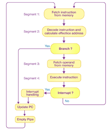
A four-stage instruction pipeline is illustrated in the block diagram above. The instruction cycle is divided into four parts:
Segment 1 The instruction fetch stage is implemented using a FIFO (first-in, first-out) buffer.
Segment 2 In this stage, the memory instruction is decoded, and the effective address is calculated in a separate arithmetic circuit.
Segment 3 Operands are fetched from memory in this stage.
Segment 4 Finally, the instruction is executed in the last stage of the pipeline.
Characteristics of Multiprocessors
A multiprocessor is a single computer that contains multiple processors. The processors in a multiprocessor system can communicate and cooperate at various levels to solve a given problem. Communication between processors occurs either by sending messages or by sharing a common memory.
The major characteristics of multiprocessors are as follows:
-
Parallel Computing − This involves the simultaneous use of multiple processors, developed with a common architecture, to execute a shared task. Typically, processors are identical and work together so that users perceive they are the only users of the system. In reality, many users are accessing the system simultaneously.
-
Distributed Computing − This involves using a network of processors. Each processor in the network can be considered a computer in its own right, capable of solving problems independently. These processors are heterogeneous, and generally, each task is assigned to a specific processor.
-
Supercomputing − This involves using the fastest machines to solve large and computationally complex problems. In the past, supercomputers were vector machines, but now parallel computing is widely adopted.
-
Pipelining − This method divides a specific task into several subtasks that are performed sequentially. Functional units execute each subtask. The units are connected serially and operate simultaneously.
-
Vector Computing − This involves using vector processors, where operations such as multiplication are divided into multiple steps and applied to a stream of operands ("vectors").
-
Systolic − Similar to pipelining, but units are not arranged in a linear order. The steps in systolic computing are generally smaller, more numerous, and executed in a lockstep manner. This technique is often used in special-purpose hardware such as image or signal processors.
Interconnection Structures
- A computer is a network of basic modules of mainly three types (Processors, Memory, I/O Modules).
- The collection of paths connecting these modules is called the Interconnection Structure.
- The design of the Interconnection Structure depends on the nature of exchanges that must be made among the modules.
Nature of exchanges needed for each type of module:
Memory: A memory consists of N words of equal length. Each word is assigned a unique numerical address (0, 1, 2, ……, N-1).
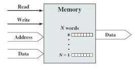
- Nature of operation (Read / Write)
- Address (location of operation)
- Data (to be written or read)
I/O Module: From the computer’s point of view, I/O is functionally similar to memory.
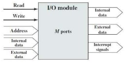
- Nature of operation (Read / Write)
- Address (Port Address – interface to each I/O device is referred to as a Port)
- Data (to and from external device)
- Data (to microprocessor)
- Interrupt (to microprocessor)
Processor: The processor reads in instructions and data.
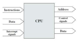
- Writes out data (to I/O or memory)
- Control signals (to subunits)
- Interrupts (from attached I/O devices)
Types:
- Bus and Multiple Bus Structure
- Point-to-Point Interconnection Structure with Packetized Data Transfer
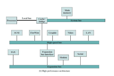
Bus Interconnection:
- A bus is a communication pathway connecting two or more devices through a shared transmission medium.
- In bus interconnection, one device at a time can transmit, and all others can receive.
- Typically, a bus consists of multiple lines, each line transmitting a single bit.
- Several lines of a bus can be used to transmit binary digits in parallel.
- A computer system contains a number of different buses to connect components at various levels of the computer system hierarchy.
- A bus that connects major components (Processor, Memory, and I/O) is called a System Bus.
- Common computer interconnection structures are based on the use of one or more System Buses.
Bus Structure:
-
A system bus consists of about fifty to hundreds of separate lines.
-
Each line is assigned a separate meaning or function.
-
These lines can be classified into three functional groups:
- Data
- Address
- Control
-
The number of lines for data determines how many bits can be transferred at a time.
-
The width of the address lines determines the maximum memory capacity of the system.
-
Control lines are used to control access to and the use of the data and address lines.
-
Control signals transmit both command and timing information among modules. Examples: Clock, Reset, Interrupt Request, Interrupt Acknowledge, Bus Request, Bus Grant, Memory Read, Memory Write, I/O Read, I/O Write, Transfer Acknowledge, etc.
Elements of Bus Design:
Bus Type:
- Dedicated: Functional or physical dedication.
- Multiplexed (Time Multiplexed): Fewer lines, so lower cost, but more complex circuitry is needed, and events that share the same lines can’t take place in parallel.
Method of Arbitration:
- Centralized: A single hardware device is the Bus Controller.
- Distributed: Each module contains access control logic.
Timing:
- Synchronous: The occurrence of events on the bus is determined by a clock.
- Asynchronous: The occurrence of events follows and depends on the occurrence of previous events.
Bus Width:
- Data Bus Width: The number of lines for data determines how many bits can be transferred at a time.
- Address Bus Width: The width of the address lines determines the maximum memory capacity of the system.
Data Transfer Type:
- Read
- Write
- Read-Modify-Write
- Read-After-Write
- Block Transfer
Interprocessor Arbitration
There is something known as a System Bus that connects the CPU, Input-Output Processor, and Memory (main components of a computer). In some cases, a dispute may arise on the System Bus such that only one of these components can access it at a time. The mechanism used to resolve this dispute is known as Interprocessor Arbitration.
Computer systems need buses to facilitate the transfer of information between their various components. On the System Bus that connects the CPU, Input-Output Processor, and Memory, only one of these components is granted access to use the bus at any given time. Hence, an appropriate priority-resolving mechanism is required to decide which processor should gain control of the bus. Therefore, a mechanism is needed to handle multiple requests for the bus, known as Interprocessor Arbitration. The arbitration procedure services all processor requests based on established priorities.
Arbitration Techniques: The following are the techniques of arbitration:
Static Arbitration Techniques
In this technique, the assigned priority is fixed. It has two types: serial arbitration procedures and parallel arbitration logic.
Serial Arbitration
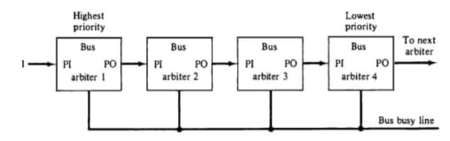
It is also known as Daisy Chain Arbitration. It is implemented by the daisy-chain connection of bus arbitration circuits. The scheme derives its name from the structure of the grant line, which chains through each device from the highest to lowest priority. The highest priority device will pass the grant line to the lower priority device only if it does not need it. Then the priority is forwarded to the next device in the sequence. All devices use the same line for bus requests. When a busy bus line returns to its idle state, the highest priority arbiter enables the busy line, and its corresponding processor can then initiate the required bus transfer.
Advantages:
- It has a simple design.
- Fewer control lines are used.
Disadvantages:
- Priority depends on the physical location of the device.
- Propagation delay due to serial granting of the bus.
- Failure of one device may cause the failure of the entire system.
- Cannot assure fairness—a low-priority device may be locked out indefinitely.
Parallel Arbitration
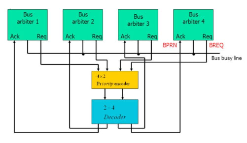
It uses an external priority encoder and decoder. Each bus arbiter has a bus request output line and a bus acknowledge input line. Each arbiter enables its request line when its processor is requesting access to the system bus. The processor with the highest priority, as determined by the output of the decoder, gains access to the bus.
Dynamic Arbitration Techniques
Serial and parallel bus arbitration techniques are static since the assigned priorities are fixed. In dynamic arbitration, the priorities of the system change while the system is in operation.
The various algorithms used are:
-
Time Slice - It allocates a fixed-length time slice of bus access to each processor in a round-robin fashion. The service provided to each system component is independent of its physical proximity to the bus.
-
Polling - In polling, the controller generates the addresses of the devices. The number of address lines needed depends on the number of connected devices in the system. The controller generates a sequence of device addresses in response to bus requests. When the requesting device recognizes its address, it activates the busy bus line and uses the bus. After several bus cycles, the polling process continues by selecting another processor. The polling sequence is usually programmable, allowing selection priority to be altered under program control.
-
Least Recently Used (LRU) - This algorithm gives the highest priority to the device that has not used the bus for the longest time. The priorities are adjusted after several bus cycles according to the LRU algorithm.
-
FIFO (First In First Out) - Requests are served in the order they are received under the FIFO scheme. The bus controller maintains a queue of bus requests and serves them accordingly. Each processor must wait for its turn to use the bus based on the order of the queue.
-
Rotating Daisy Chain - This is a dynamic extension of the daisy chain algorithm. There is no central bus controller in this scheme. The priority line is connected from the priority out of the last device back to the priority in of the first device, forming a closed loop. The priority of each arbiter for a given bus cycle is determined by its position along the bus priority line relative to the arbiter whose processor is currently controlling the bus. Once an arbiter releases the bus, it moves to the lowest priority.
Interprocess Communication & Synchronization
Interprocess communication is the mechanism provided by the operating system that allows processes to communicate with each other. This communication could involve one process informing another that an event has occurred or transferring data from one process to another.

Synchronization in Interprocess Communication Synchronization is a necessary part of interprocess communication. It is either provided by the interprocess control mechanism or handled by the communicating processes.
-
Semaphore A semaphore is a variable that controls access to a common resource by multiple processes. There are two types of semaphores: binary semaphores and counting semaphores.
-
Mutual Exclusion Mutual exclusion ensures that only one process or thread can enter the critical section at a time. This is useful for synchronization and helps prevent race conditions.
-
Barrier A barrier prevents individual processes from proceeding until all participating processes reach the barrier. Many parallel languages and collective routines use barriers.
-
Spinlock This is a type of lock where processes trying to acquire the lock wait in a loop while repeatedly checking if the lock is available. This is known as busy waiting because the process remains active without performing any useful operation.
Approaches to Interprocess Communication
-
Pipe A pipe is a unidirectional data channel. Two pipes can be used to create a two-way data channel between two processes. This method uses standard input and output mechanisms. Pipes are used in all POSIX systems as well as Windows operating systems.
-
Socket A socket is an endpoint for sending or receiving data across a network. It is used for communication between processes on the same computer or on different computers within a network. Most operating systems use sockets for interprocess communication.
-
File A file is a data record that may be stored on disk or provided on demand by a file server. Multiple processes can access a file as needed. All operating systems use files for data storage.
-
Signal Signals are a limited form of interprocess communication. They are system messages sent from one process to another. Typically, signals are not used to transfer data but are used to send remote commands between processes.
-
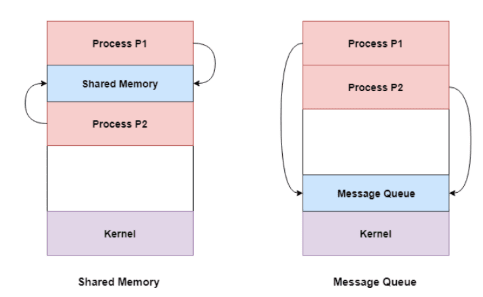
Shared Memory Shared memory is a memory space that can be accessed simultaneously by multiple processes, allowing them to communicate. POSIX-compliant systems as well as Windows operating systems use shared memory.
-
Message Queue Multiple processes can read and write data to a message queue without being directly connected to each other. Messages are stored in the queue until the recipient process retrieves them. Message queues are widely used in interprocess communication and supported by most operating systems.
Advantages
- Enables processes to communicate and share resources, leading to increased efficiency and flexibility.
- Facilitates coordination between multiple processes, improving overall system performance.
- Allows for the creation of distributed systems that can span multiple computers or networks.
- Supports the implementation of various synchronization and communication protocols, such as semaphores, pipes, and sockets.
Disadvantages
- Increases system complexity, making it harder to design, implement, and debug.
- Can introduce security vulnerabilities, as processes may access or modify data belonging to other processes.
- Requires careful management of system resources such as memory and CPU time to ensure that IPC operations do not degrade overall system performance.
- Can lead to data inconsistencies if multiple processes simultaneously access or modify the same data.