Unsigned
Unsigned numbers are numeric values that represent only non-negative quantities (zero and positive values). In the binary system, unsigned numbers are represented using only the magnitude of the value, with each bit contributing to its total. The smallest unsigned number is always zero (all bits set to 0), while the maximum value depends on the number of bits used.
Range of Unsigned Numbers in Binary System:
The range depends directly on the bit length. For an n-bit number:
- Minimum value: 0
- Maximum value: 2ⁿ - 1
Range of unsigned numbers: 0 to 2ⁿ - 1Example:
- 4-bit Number: Ranges from 0 to 15.
- 8-bit Number: Ranges from 0 to 255.
- 16-bit Number: Ranges from 0 to 65,535.
Use Cases of Unsigned Binary Representation: Unsigned binary numbers serve fundamental roles across computing systems where negative values aren't needed.
- Every byte in RAM gets a unique unsigned address. A 32-bit system can access 4GB of memory (0 to 4,294,967,295).
- RGB color values (0–255) use 8-bit unsigned numbers per channel. Image dimensions and pixel counts also rely on unsigned ranges.
- Microprocessors use unsigned values for status flags and control signals where only positive states exist.
- Packet sizes, port numbers, and IP header fields often use unsigned integers to prevent negative interpretations.
- Sensor readings (like temperature or light intensity) and timer counts utilize unsigned formats when negative measurements are impossible.
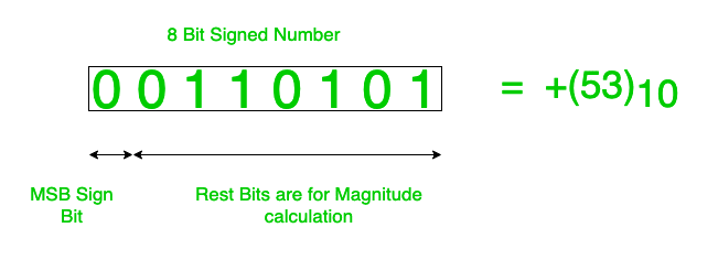
Signed and Floating-Point Data Representation
Signed data represent both positive and negative values in computing by allocating one bit (typically the MSB) as a sign indicator. In binary representation, they enable negative value storage through three primary methods:
- Sign-Magnitude
- 1's Complement
- 2's Complement
The 2's complement method dominates modern systems due to its arithmetic efficiency and absence of redundant zero representations.
Sign-Magnitude Representation
This method uses the leftmost bit as a sign flag (0 for positive, 1 for negative) while the remaining bits store the absolute value. It creates two zero representations (+0 and -0) and complicates arithmetic operations due to separate sign handling.
Range of Sign-Magnitude Representation
-2ⁿ⁻¹ + 1 to 2ⁿ⁻¹ - 1
Example: In an 8-bit system
- Decimal number +25 is represented as 00011001 (Sign bit 0, magnitude 25)
- Decimal number -25 is represented as 10011001 (Sign bit 1, magnitude 25)
Why Sign-Magnitude Fails in Practice
- Wastes a representable value by encoding both +0 (0000) and -0 (1000), creating unnecessary complexity in comparisons and arithmetic.
- Basic calculations fail because the sign bit requires separate handling. Adding positive and negative versions of the same number doesn't produce zero.
- Requires extra circuitry to manage sign bits during calculations, slowing down processors compared to complement systems.
- Effectively loses one bit of precision since the sign bit doesn't contribute to magnitude, unlike modern systems that use all bits for value representation.
1's Complement Representation
In 1's complement, negative numbers are created by flipping all bits of the positive counterpart. The leftmost bit still indicates the sign (0 for positive, 1 for negative). This method also suffers from dual zero representations (0000 as +0 and 1111 as -0) but it simplifies subtraction through bit inversion.
Range of 1's Complement Representation
-2ⁿ⁻¹ + 1 to 2ⁿ⁻¹ - 1
Example: In an 8-bit system
- Decimal number +18 is represented as 00010010
- Decimal number -18 is represented as 11101101 (All bits flipped)
Critical Flaws of 1's Complement
- Maintains two zero forms (0000 and 1111), wasting a valid number representation and complicating equality checks.
- Forces an extra addition step when carry bits overflow, making arithmetic slower than 2's complement.
- Basic math operations need sign-bit checks, creating hardware complexity modern systems avoid.
- While better than sign-magnitude, its quirks made 2's complement the universal standard for binary arithmetic.
2's Complement Representation
2's complement forms negative numbers by inverting all bits of the positive value and adding 1. The leftmost bit serves as the sign indicator while enabling single zero representation. It simplifies hardware design by allowing identical addition and subtraction operations.

Range of 2's Complement Representation
-2ⁿ⁻¹ to 2ⁿ⁻¹ - 1
Example: In an 8-bit system
- Decimal number +20 is represented as 00010100
- Decimal number -20 is represented as 11101100 (Invert bits: 11101011, then add 1)
Limitations of 2's Complement
- In a fixed-bit system, 2's complement has a limited range. For an n-bit system, it represents values from -2ⁿ⁻¹ to 2ⁿ⁻¹ - 1, restricting the number of values that can be processed.
- The range for positive numbers is smaller than for negative numbers. Negative values range from -2ⁿ⁻¹ to -1, while positive values range from 0 to 2ⁿ⁻¹ - 1, creating an imbalance.
- Overflow occurs when arithmetic operations exceed the representable range, leading to incorrect results.
- Operations like addition and subtraction become complex with sign extension, especially for numbers of different sizes.
- The zero in 2's complement has only one form, while negative numbers have a mirrored representation (e.g., -1 is 111...1), complicating algorithms like multiplication.
Floating-Point Representation helps computers handle real numbers with a large range of values, both very small and very large. The single precision format uses 32 bits, while double precision uses 64 bits, allowing for more precision and a larger range. These formats are based on scientific notation, with a sign bit, exponent, and mantissa. The following description explains terminology and primary details of IEEE 754 binary floating-point representation. The discussion is confined to single and double precision formats.
Usually, a real number in binary is represented in the following format:
ImIm-1...I2I1I0.F1F2...FnFn-1Where Im and Fn are either 0 or 1 of the integer and fraction parts respectively.
A finite number can also be represented by four integer components: a sign (s), a base (b), a significand (m), and an exponent (e). Then the numerical value of the number is evaluated as:
(-1)^s × m × b^e where m < |b|Depending on the base and the number of bits used to encode various components, the IEEE 754 standard defines five basic formats. Among the five formats, the binary32 and binary64 formats are the single precision and double precision formats respectively, in which the base is 2.
The floating-point representation is a way to encode numbers in a format that can handle very large and very small values. It is based on scientific notation where numbers are represented as a fraction and an exponent. In computing, this representation allows for a trade-off between range and precision.
Format: A floating-point number is typically represented as:
Value = Sign × Significand × Base^ExponentWhere:
- Sign: Indicates whether the number is positive or negative.
- Significand (Mantissa): Represents the precision bits of the number.
- Base: Usually 2 in binary systems.
- Exponent: Determines the scale of the number.
Number System and Data Representation
- Number Systems: The floating-point representation often uses binary (base-2) systems in digital computers. Other number systems like decimal (base-10) or hexadecimal (base-16) may be used in different contexts.
- Data Representation: This includes how numbers are stored in computer memory, involving binary encoding and the representation of various data types.
Single Precision Format
The single precision format has 23 bits for the significand (1 represents the implied bit, detailed below), 8 bits for the exponent, and 1 bit for the sign.
For example, the rational number 9 ÷ 2 can be converted to single precision float format as follows:
9(₁₀) ÷ 2(₁₀) = 4.5(₁₀) = 100.1(₂)The result is said to be normalized if it is represented with a leading 1 bit, i.e., 1.001(₂) × 2². (Similarly, when the number 0.000000001101(₂) × 2³ is normalized, it appears as 1.101(₂) × 2⁻⁶). Omitting this implied 1 on the left gives us the mantissa of the float number. A normalized number provides more accuracy than the corresponding de-normalized number. The implied most significant bit can be used to represent a more accurate significand (23 + 1 = 24 bits), which is called subnormal representation. Floating-point numbers are to be represented in normalized form.
Subnormal numbers fall into the category of de-normalized numbers. The subnormal representation slightly reduces the exponent range and can’t be normalized since that would result in an exponent that doesn’t fit in the field. Subnormal numbers are less accurate, i.e., they have less room for nonzero bits in the fraction field, than normalized numbers. Indeed, the accuracy drops as the size of the subnormal number decreases. However, the subnormal representation is useful in filling gaps in the floating-point scale near zero.
In other words, the above result can be written as (-1)⁰ × 1.001(₂) × 2², which yields the integer components as s = 0, b = 2, significand (m) = 1.001, mantissa = 001, and e = 2. The corresponding single precision floating-point number can be represented in binary as shown below:

Where the exponent field is supposed to be 2, yet encoded as 129 (127 + 2), called the biased exponent. The exponent field is in plain binary format, which also represents negative exponents using encoding (like sign magnitude, 1’s complement, 2’s complement, etc.). The biased exponent is used for the representation of negative exponents. The biased exponent has advantages over other negative representations when performing bitwise comparisons of two floating-point numbers for equality.
A bias of (2ⁿ⁻¹ - 1), where n is the number of bits used in the exponent, is added to the exponent (e) to get the biased exponent (E). So, the biased exponent (E) of a single precision number can be obtained as:
E = e + 127The range of the exponent in single precision format is -126 to +127. Other values are used for special symbols.
Note: When we unpack a floating-point number, the exponent obtained is the biased exponent. Subtracting 127 from the biased exponent allows us to extract the unbiased exponent.
Double Precision Format
The double precision format has 52 bits for the significand (1 represents the implied bit), 11 bits for the exponent, and 1 bit for the sign. All other definitions are the same as for single precision format, except for the size of various components.
-
Precision
The smallest change that can be represented in floating-point representation is called precision. The fractional part of a single precision normalized number has exactly 23 bits of resolution (24 bits with the implied bit). This corresponds to log₁₀(2²³) ≈ 6.924 ≈ 7 decimal digits of accuracy. Similarly, for double precision numbers, the precision is log₁₀(2⁵²) ≈ 15.654 ≈ 16 decimal digits.
-
Accuracy
Accuracy in floating-point representation is governed by the number of significant bits, whereas the range is limited by the exponent. Not all real numbers can be exactly represented in floating-point format. For any number that is not a floating-point number, there are two options for floating-point approximation: the closest floating-point number less than x (denoted x_) and the closest floating-point number greater than x (denoted x⁺). A rounding operation is performed on the number of significant bits in the mantissa field based on the selected mode. The round-down mode sets x to x_, the round-up mode sets x to x⁺, the round-towards-zero mode sets x to either x_ or x⁺, whichever is between x and zero, and the round-to-nearest mode sets x to x_ or x⁺, whichever is nearest to x. Usually, round-to-nearest is the most commonly used mode. The closeness of the floating-point representation to the actual value is referred to as accuracy.
-
Special Bit Patterns
The standard defines several special floating-point bit patterns. Zero cannot have a most significant 1 bit, hence it cannot be normalized. The hidden bit representation requires a special technique for storing zero. We have two different bit patterns, +0 and -0, for the same numerical value zero. For single precision floating-point representation, these patterns are given below:
0 00000000 00000000000000000000000 = +0
1 00000000 00000000000000000000000 = -0
Similarly, the standard represents two different bit patterns for +INF and -INF, shown below:
0 11111111 00000000000000000000000 = +INF
1 11111111 00000000000000000000000 = -INF
All of these special numbers, as well as other special numbers described below, are subnormal numbers, represented using a special bit pattern in the exponent field. This slightly reduces the exponent range, but this is acceptable since the range is already very large.
An attempt to compute expressions like 0 × INF, 0 ÷ INF, etc., makes no mathematical sense. The standard calls the result of such expressions "Not a Number" (NaN). Any subsequent expression involving NaN yields NaN. The representation of NaN has a non-zero significand and all 1s in the exponent field. These are shown below for single precision format (x denotes don’t care bits):
x 11111111 m0000000000000000000000Where m can be 0 or 1. This gives us two different representations of NaN:
0 11111111 00000000000000000000001 _____________ Signaling NaN (SNaN)
0 11111111 10000000000000000000001 _____________ Quiet NaN (QNaN)
Usually, QNaN and SNaN are used for error handling. QNaN does not raise any exceptions as it propagates through most operations, whereas SNaN raises an invalid exception when consumed by most operations.
Overflow and Underflow
Overflow occurs when the true result of an arithmetic operation is finite but larger in magnitude than the largest floating-point number that can be stored using the given precision. Underflow occurs when the true result is smaller in magnitude (infinitesimal) than the smallest normalized floating-point number that can be stored. Overflow cannot be ignored in calculations, whereas underflow can effectively be replaced by zero.
-
Endianness
The IEEE 754 standard defines a binary floating-point format, but the architecture details are left to hardware manufacturers. The storage order of individual bytes in binary floating-point numbers varies from architecture to architecture.
Advantages
- Wide Range: Can represent very large and very small numbers.
- Efficient Calculation: Suitable for a wide range of scientific, engineering, and graphics applications where precision and range are important.
- Standardization: Floating-point representation is standardized (IEEE 754), which ensures consistency and compatibility across different systems and programming languages.
Disadvantages
- Precision Issues: Floating-point numbers can suffer from precision errors due to rounding and truncation.
- Complexity: More complex than fixed-point representation, requiring more computational resources.
- Overhead: Operations involving floating-point numbers can be slower and require more memory compared to integer operations.
Applications
- Scientific Computations: Used in simulations, modeling, and calculations requiring high precision and large ranges.
- Graphics: Essential in rendering and manipulating graphical data where precise calculations are needed.
- Engineering: Applied in fields such as aerospace, mechanical engineering, and electronics for accurate measurements and simulations.
Addition
In computers, addition is performed by the Arithmetic Logic Unit (ALU). The two numbers to be added are stored in two separate registers. The ALU adds these two numbers and stores the result in another register. Depending on the size of the registers, this addition can be performed on 8-bit, 16-bit, 32-bit, or 64-bit numbers. This section discusses how addition is performed with different register sizes.
8-bit addition:
When two 8-bit numbers are added, the result is stored in another register. The ALU loads A’s value into its first input port and B into its second input port. It then performs the addition and stores the result in a predetermined register (Register 2). The total number of steps required is 3.
16-bit addition:
When two 16-bit numbers are added, the result can be either a 16-bit or a 32-bit number. In the 8-bit example, the result was stored in one register. In this case, the result may span two registers. For 32-bit numbers, addition or subtraction is used based on the operands. The algorithm to add 16-bit numbers is:
Let A = 16-bit number and B = 16-bit number

P1 = A XOR B
P2 = A + B
P1 and P2 are intermediate values based on A and B. After computing them, they are added to obtain the final result using an adder.
64-bit Addition:
When you add two 64-bit numbers, the result can be a 128-bit number or may include an upper 32-bit value. For example, the algorithm to add 64-bit numbers is as follows:
Let A = 64-bit number and B = 64-bit number

P1 = A XOR B
P2 = A + B
The way P1 and P2 temporaries are formed depends on the values of A and B. Once P1 and P2 are computed, they are added to obtain the final result.
Some interesting aspects of 64-bit addition include:
First, it calculates the XOR of the two numbers to compute P1 and P2. This is achieved by using a large number (8 bytes), assuming A is not greater than B. It also uses a time-honored trick of keeping track of the number of leading and trailing zeroes to compute the result efficiently without iterating through all possible combinations (i.e., 2⁶⁴ outcomes). Second, there is no carry bit in intermediate steps, so results don’t overflow 64-bit registers. Finally, the final addition can be performed using a 64-bit adder or two 32-bit additions.
Binary Addition: Next, we will discuss the binary addition of integers. Binary addition is performed by adding two numbers and storing the result in a register. The algorithm for binary addition is as follows:
Let A = [0] and B = [1]Then, A + B can be expressed as:
A + B = B << 1 | B >> 8 | B >>> 7 | B >>> 4 (6 steps). Note that if the second bit of B is 0, then the result will not be affected. The operations A + B >> 1 and A + B * 2 both lead to the same result (i.e., B << 1 and B >> 2).There are many applications of binary addition. One of the most commonly used applications is in audio and video encoding. For example, converting analog signals to digital is called sampling. The sampling rate or frequency is defined by the number of bits per second (bps) used to represent a given audio bandwidth. For example, a CD uses a sampling rate of 44,100 bps, which means it takes 44,100 samples per second for an 8 kHz bandwidth.
Arithmetic operations—addition in particular—are used daily in computers, and almost every algorithm can be expressed in some form of an arithmetic expression. For example, to find the average of a set of numbers, we could use the following formula:
Initialization: C = 0; A = [0] and B = [1]The thumb rule of binary addition is:
0 + 0 = 0
0 + 1 = 1
1 + 0 = 1
1 + 1 = 10
Examples (a–e) of unsigned binary addition are shown:

Subtraction
Subtraction is the process of finding the difference of B from A, i.e., A − B. The basis of binary subtraction is:
0 - 0 = 0
0 - 1 = -1
1 - 0 = 1
1 - 1 = 0
As with decimal subtraction, the usual borrow logic from the adjacent digit is applied. Examples of signed binary subtraction are shown below:
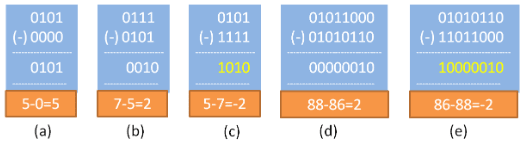
2's Complement for Subtraction
"1's complement + 1 = 2's complement"Generating the 2's complement is simple using an XOR circuit. The XOR circuit generates the 1's complement. A control signal called SUBTRACT is used to add the value of 1. This way, an adder can perform subtraction. See the example below, where case (b), case (c), and case (e) are worked out using 2's complement representation; A − B becomes A + (2's complement of B). The result is obtained in 2's complement form, discarding the carry. This method works for all types of data.

Interpreting 2's Complement Numbers
- Observe the sign bit (MSB).
- If it is '0', the number is positive; the remaining (n−1) bits represent the absolute value of the number in binary.
- If it is '1', the number is negative; the remaining (n−1) bits represent the 2’s complement of the number in binary. Invert the (n−1) bits and add 1 to get the absolute value of the negative number.
Multiplication and Division Algorithm
The multiplier and multiplicand bits are loaded into two registers, Q and M. A third register, A, is initially set to zero. C is the 1-bit register that holds the carry bit resulting from addition. Now, the control logic reads the bits of the multiplier one at a time. If Q₀ is 1, the multiplicand is added to register A, and the result is stored back in register A with the C bit used for carry. Then all the bits of CAQ are shifted one bit to the right so that the C bit goes to Aₙ₋₁, A₀ goes to Qₙ₋₁, and Q₀ is lost. If Q₀ is 0, no addition is performed—just perform the shift. The process is repeated for each bit of the original multiplier. The resulting 2n-bit product is contained in the QA register.

There are three types of operations for multiplication:
- It should determine whether a multiplier bit is 1 or 0 so that it can designate the partial product. If the multiplier bit is 0, the partial product is zero; if the multiplier bit is 1, the multiplicand is the partial product.
- It should shift the partial product.
- It should add the partial product.
Algorithm: Step 1: Clear the sum (accumulator A). Place the multiplicand in X and the multiplier in Y. Step 2: Test Y₀; if it is 1, add the content of X to the accumulator A. Step 3: Logically shift the content of X left by one position and the content of Y right by one position. Step 4: Check for completion; if not completed, go to Step 2.
Example: Multiply 7 × 6
Sum     X       Y       Count   Remarks
000000  000111  110     3       Initialization
000000  001110  011     2       Left shift X, Right shift Y
001110  011100  001     1       Sum ← Sum + X, Left shift X, Right shift Y
101010  111000  000     0       Sum ← Sum + X, Left shift X, Right shift Y
Result = 101010 = 2⁵ + 2³ + 2¹ = 42
Signed Multiplication (Booth’s Algorithm) – 2’s Complement Multiplication
The multiplier and multiplicand are placed in the Q and M registers, respectively. There is also a 1-bit register placed logically to the right of the least significant bit Q₀ of the Q register, designated as Q₋₁. The result of multiplication will appear in the A and Q registers. A and Q₋₁ are initialized to zero. If the two bits (Q₀ and Q₋₁) are the same (11 or 00), then all the bits of the A, Q, and Q₋₁ registers are shifted right by one bit. If the two bits differ, then the multiplicand is either added to or subtracted from the A register, depending on whether the two bits are 01 or 10. Following the addition or subtraction, an arithmetic right shift occurs. When the count reaches zero, the result resides in AQ in the form of a signed integer [−2ⁿ⁻¹aₙ₋₁ + 2ⁿ⁻²aₙ₋₂ + … + 2¹a₁ + 2⁰a₀].

Division Algorithm
Division is somewhat more complex than multiplication but is based on the same general principles. The operation involves repetitive shifting and addition or subtraction.
First, the bits of the dividend are examined from left to right until the set of bits examined represents a number greater than or equal to the divisor; this is referred to as the divisor being able to divide the number. Until this event occurs, 0s are placed in the quotient from left to right. When the event occurs, a 1 is placed in the quotient and the divisor is subtracted from the partial dividend. The result is referred to as a partial remainder. The division follows a cyclic pattern. At each cycle, additional bits from the dividend are appended to the partial remainder until the result is greater than or equal to the divisor. The divisor is subtracted from this number to produce a new partial remainder. The process continues until all the bits of the dividend are exhausted.

Restoring Division
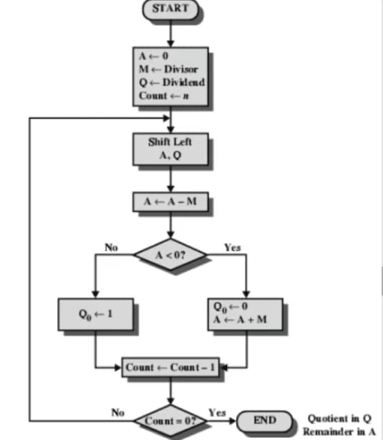
Algorithm:
Step 1: Initialize the A, Q, and M registers to zero, dividend, and divisor respectively, and set the counter to n, where n is the number of bits in the dividend.
Step 2: Shift A and Q left by one binary position.
Step 3: Subtract M from A, placing the answer back in A. If the sign of A is 1, set Q₀ to 0 and add M back to A (restore A). If the sign of A is 0, set Q₀ to 1.
Step 4: Decrease the counter. If the counter > 0, repeat the process from Step 2; otherwise, stop the process. The final remainder will be in A, and the quotient will be in Q.
Example: Divide 15 (1111) by 4 (0100)
A       Q       M       M+1     Count   Remarks
00000   1111    00100   11100   4       Initialization
00001   1110                    Shift Left A, Q
11101   1110                    Sub (A ← A − M)
00001   1110                    Q₀ ← 0, Add (A ← A + M)
00011   1100                    Shift Left A, Q
11110   1100                    Sub (A ← A − M)
00011   1100                    Q₀ ← 0, Add (A ← A + M)
00111   1000                    Shift Left A, Q
00011   1000                    Sub (A ← A − M)
00011   1001                    Set Q₀ ← 1
00110   0010                    Shift Left A, Q
00010   0010                    Sub (A ← A − M)
00011   0011            0       Set Q₀ ← 1
Quotient in Q = 0011 = 3 Remainder in A = 00011 = 3
Non-Restoring Division (Signed Binary Division) Algorithm
Step 1: Initialize A, Q, and M registers to zero, dividend, and divisor respectively, and set the count to the number of bits in the dividend.
Step 2: Check the sign of A: If A < 0 (i.e., bₙ₋₁ is 1): a. Shift A and Q left by one binary position. b. Add the content of M to A and store it back in A.
If A ≥ 0 (i.e., bₙ₋₁ is 0): a. Shift A and Q left by one binary position. b. Subtract the content of M from A and store it back in A.
Step 3: If the sign of A is 0, set Q₀ to 1; else set Q₀ to 0. Step 4: Decrease the counter. If counter > 0, repeat the process from Step 2; otherwise, go to Step 5. Step 5: If A ≥ 0 (i.e., positive), the content of A is the remainder; else, add the content of M to A to get the remainder. The quotient will be in Q.
Booth's Multiplication Algorithm
Booth's algorithm provides a procedure for multiplying binary integers in signed 2’s complement representation in an efficient way, i.e., it requires fewer additions/subtractions. It operates on the principle that strings of 0s in the multiplier require no addition but only shifting, and a string of 1s in the multiplier from bit weight 2^k to weight 2^m can be treated as 2^(k+1) − 2^m. As in all multiplication schemes, Booth's algorithm requires examining the multiplier bits and shifting the partial product. Prior to the shift, the multiplicand may be added to, subtracted from, or left unchanged in the partial product according to the following rules:
- The multiplicand is subtracted from the partial product upon encountering the first least significant 1 in a string of 1s in the multiplier.
- The multiplicand is added to the partial product upon encountering the first 0 (provided that there was a previous '1') in a string of 0s in the multiplier.
- The partial product does not change when the current multiplier bit is identical to the previous multiplier bit.
Hardware Implementation of Booth's Algorithm
The hardware implementation of Booth's algorithm requires the register configuration shown in the figure below:
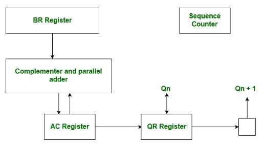
Booth's Algorithm Flowchart
We name the registers as A, B, and Q, denoted AC, BR, and QR respectively. Qₙ designates the least significant bit of the multiplier in register QR. An extra flip-flop Qₙ₊₁ is appended to QR to facilitate double inspection of the multiplier. The flowchart for Booth's algorithm is shown below:
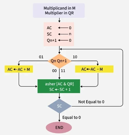
AC and the appended bit Qₙ₊₁ are initially cleared to 0, and the sequence counter (SC) is set to a number n, equal to the number of bits in the multiplier. The two bits of the multiplier, Qₙ and Qₙ₊₁, are inspected. If the two bits are equal to 10, it indicates the first 1 in a string has been encountered, requiring subtraction of the multiplicand from the partial product in AC. If the two bits are equal to 01, it indicates the first 0 in a string of 0s has been encountered, requiring the addition of the multiplicand to the partial product in AC. When the two bits are equal, the partial product remains unchanged.
Overflow cannot occur because addition and subtraction of the multiplicand follow each other. As a result, the two numbers being added always have opposite signs, a condition that avoids overflow. The next step is to shift right the partial product and the multiplier (including Qₙ₊₁). This is an arithmetic shift right (ashr) operation, which shifts AC and QR to the right and leaves the sign bit in AC unchanged. The sequence counter is decremented, and the computational loop is repeated n times.
The product of negative numbers is important. While multiplying negative numbers, we need to find the 2's complement of the number to change its sign, because it is easier to perform addition than binary subtraction. The product of two negative numbers is demonstrated below along with the 2's complement.
Example — A Numerical Example of Booth's Algorithm (n = 4)
It shows the step-by-step multiplication of −5 and −7:
BR = −5 = 1011
BR' = 0100      <-- 1's Complement (invert bits: 0 → 1, 1 → 0)
BR'+1 = 0101    <-- 2's Complement (add 1 to 1's complement)
QR = −7 = 1001  <-- 2's Complement of 0111 (7 = 0111 in binary)

Initial state:
AC = 0000, QR = 1001, Qₙ₊₁ = 0, SC = 4
Qₙ Qₙ₊₁ = 10 → Perform AC + BR'+1 → AC = 0101

After right shift of AC and QR:
AC = 0010, QR = 1100, Qₙ₊₁ = 1
Product Calculation
Product = AC QR
Product = 0010 0011 = 35
Advantages
- Faster than traditional multiplication: Booth's algorithm requires fewer steps than traditional methods to produce the same result.
- Efficient for signed numbers: Specifically designed for signed binary multiplication, it is more efficient than traditional methods.
- Lower hardware requirement: It uses fewer hardware resources, making it suitable for limited-resource environments.
- Widely used in hardware: Implemented in digital signal processors, microprocessors, and FPGAs.
Disadvantages
- Complex to understand: It is more complex to grasp and implement compared to traditional methods.
- Limited applicability: Only suited for signed binary multiplication; not usable for unsigned numbers without modification.
- Higher latency: Multiple iterations are required to compute one result, increasing delay.
- Higher power consumption: For larger inputs, it consumes more power than traditional methods.
Applications of Booth's Algorithm
- Chip and Computer Processors: Booth's algorithm is used in arithmetic logic units (ALUs) of microprocessors for efficient multiplication, especially in scientific computing, graphics processing, and cryptography.
- Digital Signal Processing (DSP): Enables efficient multiplication of large binary numbers, crucial for real-time audio, video, and signal processing.
- Hardware Accelerators: Integrated into accelerators for applications such as image processing, neural networks, and machine learning to improve multiplication speed.
- Cryptography: Used in modular exponentiation within encryption and digital signature algorithms, improving efficiency during large number multiplication.
- High-Performance Computing (HPC): Speeds up large-scale multiplications in scientific simulations and numerical computations.
- Embedded Systems: Optimizes multiplication in systems with limited processing power and memory, enhancing performance while saving energy.
- Network Packet Processing: Helps reduce processing time and energy usage in routers and network devices performing multiplication operations on packet data.
- Digital Filters and Equalizers: Accelerates multiplication of coefficients with input samples in audio and communication systems, resulting in faster and more accurate filtering.
Input Output Organization
Peripheral devices, I/O interface, Modes of data transfer - Programmed I/O, Interrupt-Initiated I/O, DMA transfer, I/O processor. Serial Communication.
Memory Unit
Memory hierarchy, processor vs. memory speed, main memory, auxiliary memories, high-speed memories, cache memory, associative memory, virtual memory, and memory management hardware.